Fireye NXD410TS Installation And Operations
Touchscreen interface
Hide thumbs
Also See for NXD410TS:
- Installation and operation manual (13 pages) ,
- Installation manual (9 pages)
Table of Contents
Advertisement
Quick Links
DESCRIPTION
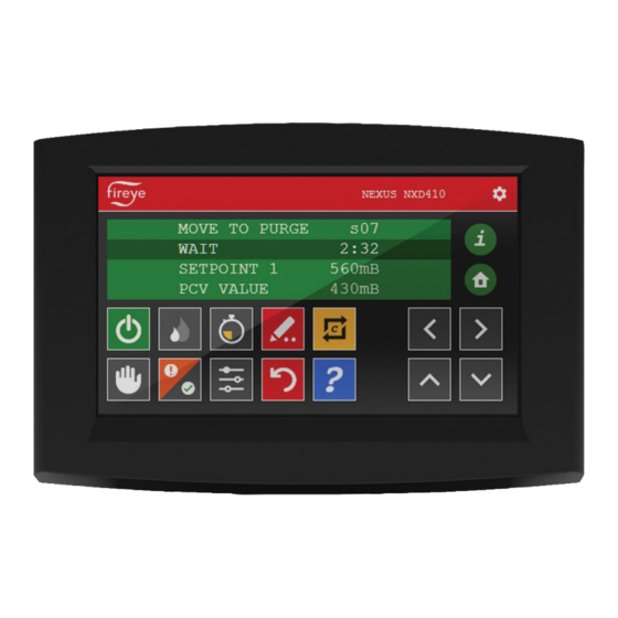
The NXD410TS provides the means to setup, monitor and display information from the NXF4000
and PPC4000 series of controls as well as any connected accessories. It provides a full touchscreen
interface for monitoring, configuration, and commissioning. The NXD410TS touchscreen is panel
mounted and connects to the NXF4000 or PPC4000 control using a serial communication cable.
NOTE: This bulletin is intended to be a supplement to bulletins NXF-4001 and PPC-4001,
which covers the installation and operation of the NXF4000 and PPC4000 controls,
respectively. Please refer to those bulletins for any specific information on installation,
features, commissioning, or operation of the connected controls.
WARNING: Failure to properly install, operate, or commission the equipment in this
manual could result in significant property damage, severe injury, or death. It is the
responsibility of the owner or user to ensure that the equipment described is installed,
operated, and commissioned in compliance with this manual and other system component
manuals, as well with all applicable national and local codes.
WARNING: Boiler operation, maintenance, and troubleshooting shall only be conducted
by trained personnel. Persons troubleshooting lockouts or resetting the control must
respond properly to troubleshooting error codes as described in this product bulletin.
Jumpers being used to perform static test on the system must only be used in a controlled
manner and must be removed prior to the operation of the control. Such tests may verify
the external controllers, limits, interlocks, actuators, valves, transformers, motors, and
other devices are operating properly. Such tests must be conducted with manual fuel
valves in the closed position only. Replace all limits and interlocks not operating properly,
and do not bypass limits in interlocks. Failure to follow these guidelines may result in an
unsafe condition hazardous to life and property.
© 2023 Carrier
Touchscreen Interface
Installation and Operation
NXD-4102
May 15, 2023
NXD410TS
1
Advertisement
Table of Contents

Subscribe to Our Youtube Channel
Related Manuals for Fireye NXD410TS


Summary of Contents for Fireye NXD410TS
-
Page 1: Description
Installation and Operation DESCRIPTION The NXD410TS provides the means to setup, monitor and display information from the NXF4000 and PPC4000 series of controls as well as any connected accessories. It provides a full touchscreen interface for monitoring, configuration, and commissioning. The NXD410TS touchscreen is panel mounted and connects to the NXF4000 or PPC4000 control using a serial communication cable. -
Page 2: Table Of Contents
Table of Contents DESCRIPTION ............................1 ORDERING INFORMATION ........................3 MOUNTING NXD410TS ..........................4 Method..............................4 Cutout ..............................5 Template .............................. 5 WIRING ..............................6 Terminals .............................. 6 Wiring ..............................7 OPERATION .............................. 8 Quick Keys ............................9 Home Screen - Main Display ........................11 Information Screen –... -
Page 3: Ordering Information
Touchscreen interface, 4.3 inch diagonal screen size, 24VDC, for use with NXD410TS NXF4000 or PPC4000 parallel positioning system Accessories Cable to connect NXD410TS to NXF4000 or PPC4000, separate power and 59-561 communication, sold by the foot. 60-3008 Bezel adapter kit to retrofit NXD410TS to cut out for NXD410. -
Page 4: Mounting Nxd410Ts
MOUNTING NXD410TS Method The NXD410TS requires a non-symmetrical cutout and is secured using two knurled-head thumb nuts. Refer to the figure below for the layout of these thumb nuts. View of NXD410TS showing placement of the knurled-head thumb nuts (one on each side) The thumb nuts attach to threaded posts which are threaded into inserts on each side of the screen. -
Page 5: Cutout
60-3008 Adapter is available for NXD410TS to NXD410 Cutout This adapter allows mounting of the NXD410TS user interface to a cutout that was previous used for the NXD410 user interface. This adapter is required due to smaller dimensions of the NXD410TS. -
Page 6: Wiring
WIRING Terminals The recommended cable (59-561) contains six wires: two power wires (18AWG) and four communication wires (22AWG) in two twisted pairs. There is also a drain wire. The figures below show the connectors for both power and communications. Power Communications The connector labeled 24V supplies the 24VDC power to the unit. -
Page 7: Wiring
Wiring If the NXD410TS is being used to replace the NXD410, the existing 59-562-2 cable can be used simply by removing and discarding the DSUB connector on the terminal end. The cable itself is identical and may be reused. The wiring between the devices is shown in the table below:... -
Page 8: Operation
The next section shows the various symbols and their functions. The NXD410TS contains a number of Quick Keys that allow the user to access that function directly. For these Quick Keys to operate, the installer or operator must first access the KEYPAD SETUP menu where the user defines if a Quick Key is used or unused. -
Page 9: Quick Keys
Quick Keys Button Key Name Description Used to turn the burner on or off. The button changes from gray to green when the burner is in the ON mode. BURNER ON This button can be enabled via the KEYPAD SETUP menu. - Page 10 Quick Keys Button Key Name Description In modify mode the button changes from red to green. In MODIFY/SAVE this mode changes to a value are allowed. Pressing again restores the button to red and saves the entry. Used to navigate up and down through the menu structure. When in modify mode these are used to UP/DOWN increment/decrement the values.
-
Page 11: Home Screen - Main Display
Home Screen - Main Display This Home screen may be accessed at any time by selecting the “Home” Icon. Select the up/down arrow keys to scroll the menu and right/left arrow keys to enter sub menus. Information Screen – Icon Display The Info screen may be accessed at any time by selecting the “I”... -
Page 12: Icon Description Screen
Icon Description Screen Select the key describes each key/icon function. Select the up/down arrow keys to scroll the menu. Manual Keys On Auto/Manual (hand) key will highlight when in manual mode then using the pencil (write) key and up/down arrow keys changes the modulation rate. Selecting the pencil (write) key again will hold at the current modulation setting. -
Page 13: Sequencing Key Function
Sequencing Key Function Sequencing key is highlighted green indicating lead boiler. Sequencing key flashes while waiting to establish as lead boiler. Adjust Menu Screen Selecting the Adjust Menu key jumps to the setpoint screen. It is possible to modify values in this menu by highlighting the value using the up/down arrow keys. Selecting the pencil (write) key will jump to passcode setup screen. -
Page 14: Low Fire Hold Key
Low Fire Hold Key Selecting the low fire key modulates to low fire hold. Selecting the low fire hold key again will release to auto. Lockout Screen A Lockout occurred on Digital Input 1. It is the 528 lockout. © 2023 Carrier... -
Page 15: Lockout Error Screen
Lockout Screen Arrow key down shows the Error code and Time and date of fault. Highlighting the Lockout or E-CODE and selecting the “?” key further information will be displayed. Selecting the Backward arrow key resets the Lockout. Lockout Error Screen When help is selected lock out table is shown as found in the NXF-4001/PPC-4001 manuals. -
Page 16: Lockout Description Screen
Lockout Description Screen Selecting an error cell in the chart above results in further details. Selecting the green check key will revert- back to error code screen and selecting X will revert-back to the Lockout screen. © 2023 Carrier... -
Page 17: Adjust Ratio Screen
Adjust Ratio Screen Display color when in Adjust Ratio Mode Entering adjust ratio is done with the burner. Key/switch on and in auto by selecting the commissioning key. Commissioning Screen Display color in Commissioning Mode Entering commissioning must be done with the burner. Key/switch off by selecting the commissioning key. -
Page 18: Run/Check Screen
Run/Check Screen Run Check on – Note the fault history/run check button bottom right hand corner is green. Fault History Screen Fault History on – Note fault history top left button has been selected. © 2023 Carrier... -
Page 19: Dvr Screen
DVR Screen DRV recording in progress – Note the icon adjacent to Fireye logo in the title bar. Remote Virtual Connection Screen Remote Virtual Network Connection in progress – Note the Eye adjacent to Fireye logo in the title bar. -
Page 20: Terminating Virtual Connection Screen
Terminating Virtual Connection Screen Selecting the Eye icon terminates the VNC client connection. Language Selection Screen Select the gear icon top righthand corner, select folder icon to access. Select X to exit. © 2023 Carrier... -
Page 21: Language Chinese
Language Chinese Select the Chinese radio button option. Language Spanish Select the Spanish Radio Button. © 2023 Carrier... -
Page 22: Screen Saver
Screen Saver Screen Saver Options Select folder icon to access. Select X to exit. Network Screen Network Option Select folder icon to access. Select X to exit. Change to desired values then select check mark to save. © 2023 Carrier... -
Page 23: Dvr & Usb Screen
All buttons disabled (dark blue, like the ‘stop’ button) when there is NO USB drive attached. Stop is only enabled during recording. Record is only enabled when not recording. Data playback can be accomplished by using NXD410TS Theme Editor. OEM Reset Accessed by clicking on the OEM logo when in the OPTIONS screen. - Page 24 OEM Reset When the PASSCODE ‘903’ is entered, the following screen is displayed. Note: This can have multiple options, such as being able to change between NXD410TS and NXTSD mode these are disabled at present. Selecting green check above or when the Network IP/Sub Mask/Gateway settings are changed and accepted prompts for a re-start.
-
Page 25: Oem Screen
OEM Screen Upon reboot, the OEM selection screen is displayed. If you’ve used the theme editor to create your own OEM, this will also appear. If a USB drive is connected upon power up and update files are detected, the user will be prompted to install each. - Page 26 Theme Editor is used to customize digital input lockout messages and playback DVR data utilizing a USB Thumb drive. © 2023 Carrier...
-
Page 27: Certifications Nxd410Ts
CERTIFICATIONS NXD410TS UL File # MP1537 The products have been designed for use in an industrial environment in compliance with the 2014/30/EU EMC Directive. The installation of these devices into the residential, commercial, and light-industrial environments is allowed only in the case that special measures are taken in order to ensure conformity to EN 61000-6-3. -
Page 28: Notice
Fireye guarantees for one year from the date of installation or 18 months from the date of manufacture, whichever occurs first, to replace, or at its option, to repair any product or part thereof which Fireye, in its sole discretion, deems to be defective in material or workmanship or which otherwise fails to conform to the description of the product on the face of its sales order.
Need help?
Do you have a question about the NXD410TS and is the answer not in the manual?
Questions and answers