Table of Contents
Advertisement
Quick Links
INSTRUCTION MANUAL
Heavy Electric Utility Heater
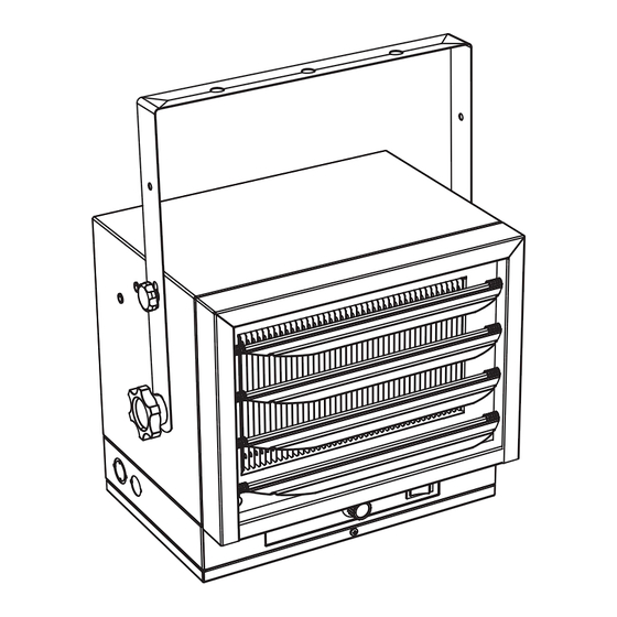
Model:HA24-75M
Figure 1
PET OWNERS WARNING:
The health of some small pets
including birds are extremely sensitive to the fumes produced during
the first-time use of many appliances. These fumes are not harmful to
humans but we recommended that you do not use your heater around
birds and small pets during its initial use until the manufacturing
corrosion coatings burn off.
Technical Support: 1-866-206-0888
Service email: info@mecanair.net
1
Advertisement
Table of Contents

Related Manuals for ProFusion HA24-75M


Summary of Contents for ProFusion HA24-75M
- Page 1 INSTRUCTION MANUAL Heavy Electric Utility Heater Model:HA24-75M Figure 1 PET OWNERS WARNING: The health of some small pets including birds are extremely sensitive to the fumes produced during the first-time use of many appliances. These fumes are not harmful to...
-
Page 2: Important Instructions
IMPORTANT INSTRUCTIONS When using electrical appliances, basic precautions should always be followed to reduce the risk of fire, electric shock, and injury to persons, including the following: 1. Read all instructions before installing or using this heater 2. This heater is hot when in use. To avoid burns, do not let bare skin touch hot surfaces Keep combustible materials, such as furniture, pillows, bedding, papers, clothes, etc. -
Page 3: Specifications
DESCRIPTION Electric utility heaters are designed to meet a variety of heating requirements by switching a few wires located in the base of the unit. Heat output is 25 589 BTU per hour. Features horizontal and vertical flow horizontal air flow. Built-in thermostat with overheating safety thermal cutout SPECIFICATIONS Rating... -
Page 4: Locating Heater
5. The mounting structure and the anchoring hardware must be capable of reliably supporting the weight of the heater and if used the mounting bracket. 6. All electrical power must be disconnected and the main service box must be locked before inspecting cleaning or servicing the hater. -
Page 5: Front View
MINIMUM MINIMUM 10 in. 14in. DISTANCE DISTANCE 24 in. 4 in. 4 in. TO WALL TO WALL 7 in. 13in. MINIMUM DISTANCE 12 in. FROM DISCHARGE TO ANY 1 in. OBJECT MINIMUM Note: Min.clearance to ceiling in. ., DISTANCE when note using mounting brackets TO FLOOR 8 ft. -
Page 6: Hanging The Heater
3. Place a washer on screws before inserting through the holes in the mounting bracket and screw them securely into a ceiling joist. NOTE: If you want to swivel the heater either to the right or left adding a washer to both sides of the bracket is recommended. - Page 7 2. To tilt the unit vertically, loosen the bracket screws (see figure 5). NOTE: For the heater to be tilted vertically, it must be mounted in bottom keyhole slots of mounting brackets to maintain adequate clearance and prevent possible overheating. 1.
-
Page 8: Mounting The Bracket
Wall mounting(optional) MOUNTING THE BRACKET Refer to Figures 5 to 1. Locate the bracket on the walll , this heater must be securely fastened. 2. Sliding the support plate into the tripod and alignment square hole,locked with screws. 3. Fixed the bracket on the wall. 4.Fixed the gibbet on the machine ,and adjusted angle with BOTTOM KEYHOLE, 5.Insttall the heater on the bracket with screw,heater must be securely fastened 6.Adjust the horizontal angel refer to Figres 5E... - Page 9 5.There are 3 angels to be selected by two screw WALL screw screw screw 45° 45° horizontal Figure 5E NOTE: The louvers are designed so they cannot be completely closed. Do not attempt to defeat this feature; damage to the unit can result. To prevent possible electric shock, disconnect power to the heater at the main service box before attempting to adjust the heat output of this unit.
-
Page 10: Connecting The Power
CONNECTING THE POWER HEATER HEATER MAX.FUSE MIN.WIRE SIZE RATING&VOLTAGE AMPS SIZE 75°C COPPER 7500W@240W 31.3 AC240V/60Hz Temperature control L 2 L 2 External control switch Power light Over heat L 1 L 1 Terminal station Caution light Contactor Motor Terminal station coil voltage 240v 60Hz 240v... - Page 11 External temperature control wiring diagram External Temperature control AC240V/60Hz Temperature control L 2 L 2 External control switch Power light Over heat L 1 L 1 Terminal station Caution light Contactor Motor Terminal station coil voltage 240v 60Hz 240v 7500W Switch 5000W 3.
- Page 12 The external thermostat installation as below: 1.prize up the hole 2.Screw out the two screws 3.Strip away the cover of wire for 50mm 5.twisted into a circle 4.Tightening the wire 7.Conected the wires to machine 6. 6.Put in the wires through the hole Put in the wires through the hole and make it secured...
-
Page 13: Back View
9.Normal control and external thermostat 8.Lock screw control(use the button switch on/off) external thermostat control Normal control Switch on the heater is Switch off the hether is in in Normal control external thermostat control BACK VIEW TO PROTECT THE HEATING ELEMENT When start the heater, turning the temperature control in clockwise slowly to terminal, the unit starts the fan first then star the heating element. - Page 14 Warning: This appliance must be grounded! Warning: The appliance must connect to a current protection circuit or device at 50Amp or less before being connected to power supply! 1. Remove the screw from the front of the unit to connect the power to the heater. 2.
-
Page 15: Setting The Thermostat
OPERATING INSTRUCTIONS THERMOSTAT SELECTION SWITCH CAUTION INDICATOR (red) Figure 8 External temperature control switch WARNING: the heater must be properly installed before it is used. SETTING THE THERMOSTAT 1) Rotate thermostat knob clockwise to high position, POWER INDICATOR will turn 2) After room reaches desired comfort level rotate thermostat knob counter clockwise until the thermostat to OFF position.yellow. - Page 16 Instruction for external thermostat control mode external thermostat control mode: Under the Select the "-" key, you can use an external temperature control function “O” “ ” external thermostat control mode Normal mode BACK VIEW...
Need help?
Do you have a question about the HA24-75M and is the answer not in the manual?
Questions and answers