Table of Contents
Advertisement
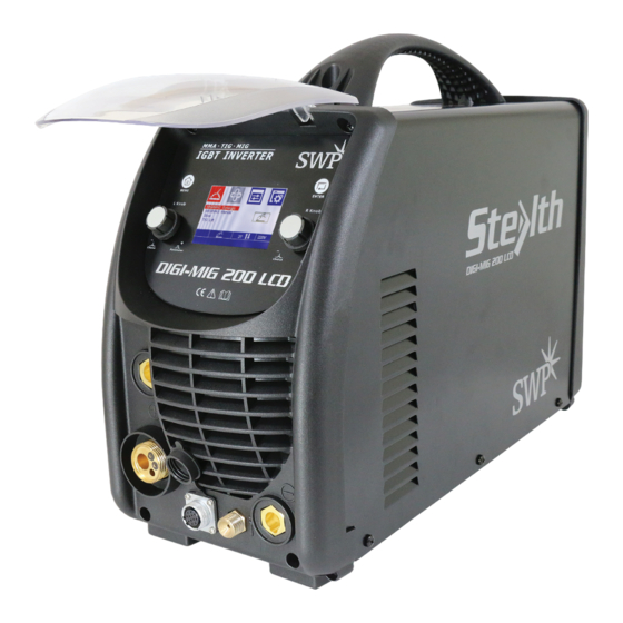
OPERATORS' MANUAL
DIGI-MIG 200 LCD
Part No. 9005H
IMPORTANT
Please read these instructions carefully before attempting to use this equipment.
Retain this manual and keep it to hand for quick reference. Pay particular attention to the safety instructions.
Contact your distributor if you do not fully understand this manual.
Advertisement
Table of Contents
Troubleshooting

Subscribe to Our Youtube Channel
Related Manuals for Stealth DIGI-MIG 200 LCD


Summary of Contents for Stealth DIGI-MIG 200 LCD
- Page 1 OPERATORS’ MANUAL DIGI-MIG 200 LCD Part No. 9005H IMPORTANT Please read these instructions carefully before attempting to use this equipment. Retain this manual and keep it to hand for quick reference. Pay particular attention to the safety instructions. Contact your distributor if you do not fully understand this manual.
-
Page 2: Table Of Contents
CONTENT §1 Safety .................... 1 §1.1 Signal Explanation ......................1 §1.2 Arc Welding Damage ....................1 §1.3 The knowledge of Electric and Magnetic Fields ............5 §2 Overview ..................7 §2.1 Brief Introduction ......................7 §2.2 Working Principle ......................8 §2.3 Volt-Ampere Characteristic .................. -
Page 3: Safety
SAFETY 1 Safety § §1.1 Signal Explanation — The above signals mean warning! Notice! Running parts and getting an electric shock or thermal parts will take damage for your body or others. The corresponding notices are as follows. It is quite a safe operation after taking several necessary protection measures. - Page 4 SAFETY Ensure to install the equipment correctly and ground the work or metal to be welded to a good electrical (earth) ground according the operation manual. —The electrode and work (or ground) circuits are electrically “hot” when the welder is on. Do not touch these “hot” parts with your bare skin or wet clothing. Wear dry, hole-free gloves to insulate hands.
- Page 5 SAFETY degreasing, cleaning or spraying operations. The heat and rays of the arc can react with solvent vapors to form phosgene, a highly toxic gas, and other irritating products. — Shielded gases used for arc welding can displace air and cause injury or death. Always use enough ventilation, especially in confined areas, to insure breathing air is safe.
- Page 6 SAFETY Do not spill fuel when filling tank. If fuel is spilled, wipe it up and do not start engine until fumes have been eliminated. WELDING SPARKS can cause fire or explosion. — Remove fire hazards from the welding area. If this is not possible, cover them to prevent the welding sparks from starting a fire.
-
Page 7: The Knowledge Of Electric And Magnetic Fields
SAFETY Rotating parts may be dangerous. — Use only compressed gas cylinders containing the correct shielding gas for the process used and properly operating regulators designed for the gas and pressure used. All hoses, fittings, etc. should be suitable for the application and maintained in good condition. - Page 8 SAFETY — Never coil the power cable around your body. — Make sure welding machine and power cable to be far away from the operator as far as possible according to the actual circumstance. — Connect the work cable to the work-piece as close as possible to the area being welded.
-
Page 9: Overview
§2 Overview §2.1 Brief Introduction MIG SERIES arc welding machine adopts the latest pulse width modulation (PWM) technology and insulated gate bipolar transistor (IGBT) power module, which can change work frequency to medium frequency so as to replace the traditional hulking work frequency transformer with the cabinet medium frequency transformer. -
Page 10: Working Principle
§2.2 Working Principle The working principle of MIG SERIES arc welding machine is shown as the following figure. Single-phase 110V/220V work frequency AC is rectified into DC, then is converted to medium frequency AC by inverter device (IGBT), after reducing voltage by medium transformer (the main transformer) and rectifying by medium frequency rectifier (fast recovery diodes), and is outputted by inductance filtering. - Page 11 (V) Volt-ampere characteristic The relation between the rated loading Working point voltage and welding current (A) §2.4Principles of welding - 9 -...
-
Page 12: Installation And Adjustment
§3 Installation and Adjustment §3.1 Parameters Model POWER MIG 200 LCD Parameters Input Voltage(V) 1~110/120/130±10% 1~220/230/240±10% Input Current(A) 37 MIG 28 MMA 28 TIG 28 MIG 32 MMA 22 TIG Input Power(KW) 4.0 MIG 3.1 MMA 3.1 TIG 6.2 MIG 7.3 MMA 4.9 TIG 25-140 (MIG) 25-200 (MIG) Welding Current(A)... -
Page 13: Equipment Connection
The relation between the duty cycle “X” and the output welding current “I” is shown as the right figure. If transformer is over-heat, the heat relay inside it will open and will output an instruction to circuit board, cut AC relay and the output welding current, and brighten the over-heat pilot lamp in the front panel. - Page 14 Operation Steps: 1、Connect the power source input cable of welding machine with the output port of air switch in electric box on the spot. 2、Connect the cable plug of wire feeder to the positive output of welding machine. 3、Connect the control cable plug of wire feeder to the aero socket on the front board of welding machine.
-
Page 15: Maintenance Of Mig Gun Mechanism
§3.4 Maintenance of MIG Gun mechanism §3.4.1 Dissection graphics for the MIG GUN I FT0063 螺丝 M 4X6 UNI 6107 §3.4.2 The parts list for the MIG GUN I HJ0645 二氧化碳欧式后把套 导电嘴扳手 I C G 6000 I HJ0028 电缆护套 12- 16- 25 M M Q 带绝缘层送丝管0. - Page 16 OPERATION §3.4.3 The operation for the MIG GUN 1. Service the wire feed mechanism at least every time the reel is changed. ·Check the wear of the feed roll groove and change the feed roll when necessary. ·Clean the welding gun wire guide with compressed air. 2.
-
Page 17: Operation
OPERATION §4 Operation §4.1 Layout for the front and rear panel: 1. MIG GUN Connect. 2. Output anode: When TIG mode, this polarity must connect the work piece 3. TIG gun control connector. 4.TIG GAS Connector 5. Output cathode:When MIG mode, this polarity must connect the work piece 6. -
Page 18: Welding Operation
OPERATION §4.2Welding operation: Main Start-up Interface (POWER MIG 200 LCD): 1. Function selection interface: rotate L Knob in the interface to choose from the four welding methods of MIG/MAG Synergic, MIG/MAG Manual, Stick and TIG Lift. 2. Synergic parameter selection interface: a synergic parameter may be selected by rotating L Knob in the interface. - Page 19 OPERATION currently used (2T/4T). 7. Synergic parameter display interface: an interface displaying the synergic parameters currently used (only available when MIG/MAG Synergic welding method is selected). 8. Multifunction display interface: an interface displaying the contents corresponding to those selected by users, such as icons of welding method, welding mode and parameter, parameter values, etc.
- Page 20 OPERATION 3. Selection and setting of welding parameters: 1) In the main interface, press the MENU key to enter the welding parameter setting interface; 2) In the welding parameter setting interface, rotate L Knob to select the parameter as required and rotate R Knob to set a value for the parameter.
- Page 21 OPERATION Operation of the MIG/MAG Manual welding method: §4.2.2 1. Selection of the welding method: 1) In the main interface, press the MENU key to enter the function selection interface; 2) In the function selection interface, rotate L Knob to select the MIG/MAG Manual welding method and press down it for confirmation as shown in Fig.
- Page 22 OPERATION Operation of the Stick welding method: §4.2.3 1. Selection of the welding method: 1) In the main interface, press the MENU key to enter the function selection interface; 2) In the function selection interface, rotate L Knob to select the Stick welding method and press it for confirmation.
- Page 23 OPERATION 3. Setting of welding voltage: 1) Press the ENTER key to enter the welding interface shown below: 2) In the welding interface, rotate L Knob to set the welding current (10 - 200 A), and then press it for confirmation; Operation of the TIG Lift welding method: §4.2.4 1.
- Page 24 OPERATION 3. Setting of welding current: 1) Press the ENTER key to enter the welding interface as shown below: 2) In the welding interface, rotate L Knob to set the welding current (10 - 200 A), and then press it for confirmation;...
-
Page 25: Welding Parameters
OPERATION §4.3Welding parameters Welding current (A) Material Wire diameter (mm) Fe-metal Solid-cored 25-90 Fe-metal Solid-cored 40-150 Fe-metal Solid-cored 50-180 Fe-metal Solid-cored 60-200 Fe-metal Solid-cored 25-110 Fe-metal Solid-cored 40-180 Fe-metal Solid-cored 50-200 Fe-metal Solid-cored 60-200 Fe-metal Flux-cored 60-160 Fe-metal Flux-cored 60-180 Fe-metal Flux-cored 70-200 Ss-metal Solid -cored... - Page 26 OPERATION ▲Connect the ground wire with the machine directly and refer to §3.5. ▲ Ensure that the input is single-phase:50/60Hz, 110V/220V±10%. ▲Before operation, no concerned people should be left. Do not watch the arc in unprotected eyes. ▲ Ensure good ventilation of the machine to improve duty ratio. ▲...
-
Page 27: Maintenance & Troubleshooting
MAINTENANCE AND TROUBLESHOOTING §5 Maintenance & Troubleshooting §5.1 Maintenance In order to guarantee that arc welding machine works high-efficiently and in safety, it must be maintained regularly. Let customers understand the maintenance methods and means of arc welding machine more , enable customers to carry on simple examination and safeguarding by oneself, try one's best to reduce the fault rate and repair times of arc welding machine, so as to lengthen service life of arc welding machine .Maintenance items in detail are in the following table. -
Page 28: Troubleshooting
MAINTENANCE AND TROUBLESHOOTING Using the dry compressed air to clear the inside of arc welding machine. Especially for clearing up the dusts on radiator, main voltage transformer, inductance, IGBT module, the fast recover diode and PCB, etc. Monthly Check up the bolt in arc welding machine, if it is loose, please screw down it. examination If it is skid, please replace. - Page 29 MAINTENANCE AND TROUBLESHOOTING If there are some simple troubles of MIG SERIES welding machine, you can consult the following Chart: Troubles Reasons Solution Breaker damaged Change it Close the breaker, but the Fuse damaged Change it power light isn’t on Power damaged Change it After welding machine is...
-
Page 30: Electrical Schematic Drawing
MAINTENANCE AND TROUBLESHOOTING §5.3Electrical schematic drawing - 28 -...
Need help?
Do you have a question about the DIGI-MIG 200 LCD and is the answer not in the manual?
Questions and answers