
Subscribe to Our Youtube Channel
Related Manuals for Miller Electric PC-300


Summary of Contents for Miller Electric PC-300
- Page 1 OM-898 128 899D July 1996 Processes TIG (GTAW) Welding Description Pulser Control PC-300 Visit our website at www.MillerWelds.com...
- Page 2 Welding Process Manuals such as SMAW, GTAW, GMAW, and GMAW-P. Miller Electric manufactures a full line of welders and welding related equipment. For information on other quality Miller products, contact your local Miller distributor to receive the latest full line catalog or individual catalog sheets.
-
Page 3: Table Of Contents
TABLE OF CONTENTS SECTION 1 – SAFETY PRECAUTIONS - READ BEFORE USING ......1-1. -
Page 5: Section 1 - Safety Precautions - Read Before Using
SECTION 1 – SAFETY PRECAUTIONS - READ BEFORE USING som _nd_5/97 1-1. Symbol Usage Means Warning! Watch Out! There are possible hazards with this procedure! The possible hazards are shown in the adjoining symbols. This group of symbols means Warning! Watch Out! possible Y Marks a special safety message. - Page 6 ARC RAYS can burn eyes and skin. BUILDUP OF GAS can injure or kill. D Shut off shielding gas supply when not in use. Arc rays from the welding process produce intense D Always ventilate confined spaces or use visible and invisible (ultraviolet and infrared) rays that can burn eyes and skin.
-
Page 7: Additional Symbols For Installation, Operation, And Maintenance
1-3. Additional Symbols For Installation, Operation, And Maintenance FIRE OR EXPLOSION hazard. MOVING PARTS can cause injury. D Do not install or place unit on, over, or near D Keep away from moving parts such as fans. combustible surfaces. D Keep all doors, panels, covers, and guards D Do not install unit near flammables. -
Page 8: Emf Information
1-5. EMF Information Considerations About Welding And The Effects Of Low Frequency 1. Keep cables close together by twisting or taping them. Electric And Magnetic Fields 2. Arrange cables to one side and away from the operator. Welding current, as it flows through welding cables, will cause electro- magnetic fields. -
Page 9: Section 2 - Specifications
SECTION 2 – SPECIFICATIONS 2-1. Pulse Control Specification Description Overall Dimensions Height: 7-1/8 in (181 mm); Width: 9-1/4 in (235 mm); Length: 5-1/2 in (140 mm) Weight Net: 7.2 lb (3.3 kg); Ship: 8.8 lb (4 kg) Input Power Cord With Plug 8 ft (2.4 m) Additional Required Equipment Welding Power Source And High-Frequency Unit... -
Page 10: Mounting Bracket Installation
3-2. Mounting Bracket Installation Pulser Control Tools Needed: Mounting Bracket 1/4, 3/8 in Bracket may be installed as shown or it may be turned outward. 5/32, 3/16 in Welding Power Source Cover If welding power source has an external high-fre- quency unit, it may be desirable to install pulser Mounting Holes control on the high-frequency unit. -
Page 11: Remote 14 Receptacle Information And Connections
3-4. Remote 14 Receptacle Information And Connections Remote 14 Receptacle RC1 Keyway Plug Threaded Collar To connect to this receptacle, align keyway, insert plug, and tighten threaded collar. C L N REMOTE 14 Socket Information: AMPERAGE Contactor control switch connection. Contactor control switch connection. -
Page 12: Section 4 - Operation
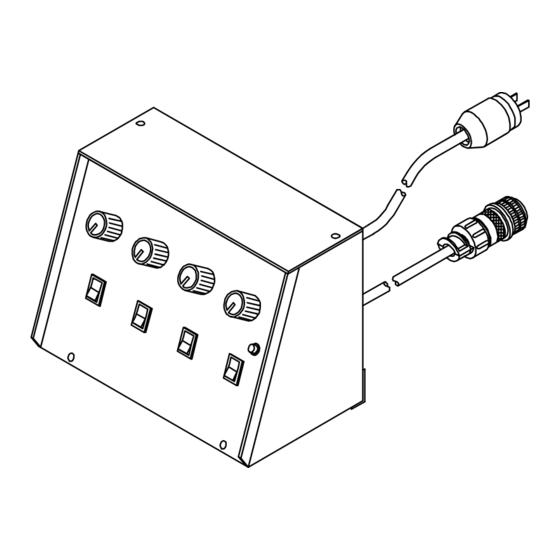
SECTION 4 – OPERATION 4-1. Controls Peak Amperage Control Background Amperage Control Pulses Per Second Control % On Time Control Pilot Light Power Switch Pulser Switch Output (Contactor) Switch Amperage Control Switch SB-130 261-A 4-2. Examples Of Pulsed Output Waveforms Pulsed Output With 50% On Time 50% On Time... -
Page 13: Peak Amperage Control
4-3. Peak Amperage Control Peak Amperage Control This control is a fine amperage con- trol for the Amperage control on the welding power source. The scale around the control is for reference only. This control can be adjusted while welding. In Example: Output Range = Min to 150 A Set Control On Welding... -
Page 14: On Time Control
4-6. % On Time Control % On Time Control Use this control as a way of select- ing pulse width (peak amperage output time of one pulse). The scale surrounding the control ranges from 5 to 95 percent. Pulser switch (see Section 4-10) must be in the On position. -
Page 15: Output (Contactor) Switch
4-9. Output (Contactor) Switch Output (Contactor) Switch Use switch to select way of control- ling unit output. Availability of open- circuit voltage depends on the posi- tion of the Pulser Control Output (Contactor) switch and the position of the welding power source Output (Contactor) switch (see Section 4-8). -
Page 16: Power Switch And Pilot Light
4-11. Power Switch And Pilot Light Power Switch Pilot Light Use this switch to turn unit and pilot light On and Off. SECTION 5 – MAINTENANCE & TROUBLESHOOTING 5-1. Routine Maintenance 3 Months Turn Off all power before maintaining. Replace Unreadable Labels Section... -
Page 17: Troubleshooting
5-2. Troubleshooting Trouble Remedy No pulsing. Secure cord connections (see Section 3-5). Be sure Power switch is On (see Section 4-11). Be sure Pulser switch is On (see Section 4-10). If remote control is not used, place Amperage switch in Panel position. If remote control is used, place switch in Remote 14 position, and be sure remote control is connected to Remote 14 receptacle (see Sec- tions 4-7 and 3-4). -
Page 18: Section 6 - Selecting And Preparing Tungsten Electrode
SECTION 6 – SELECTING AND PREPARING TUNGSTEN ELECTRODE gtaw 7/97 NOTE For additional information, see your distributor for a handbook on the Gas Tungsten Arc Welding (GTAW) process.Wear clean gloves to prevent contamination of tungsten electrode. 6-1. Selecting Tungsten Electrode ♦... -
Page 19: Preparing Tungsten For Ac Or Dc Electrode Positive (Dcep) Welding
6-2. Preparing Tungsten For AC Or DC Electrode Positive (DCEP) Welding Tungsten Electrode Balled End Y Understand follow safety symbols at start of Section NO TAG before pre- paring tungsten. Ball end of tungsten before welding 1-1/2 Times by applying either an ac amperage Electrode Diameter slightly higher than what is recom- mended for a given electrode diam-... -
Page 20: Section 7 - Parts List
SECTION 7 – PARTS LIST Item Dia. Part Mkgs. Description Quantity Figure 7-1. Main Assembly ... . . 073 562 POTENTIOMETER, C sltd sft 1/T 2W 10K ohm ..... . . - Page 21 Notes...
- Page 22 Notes...
- Page 23 Call LIMITED WARRANTY – Subject to the terms and conditions APT, ZIPCUT & PLAZCUT Model Plasma Cutting below, Miller Electric Mfg. Co., Appleton, Wisconsin, warrants Torches 1-800-4-A-MILLER to its original retail purchaser that new Miller equipment sold...
- Page 24 Contact the Delivering Carrier for: File a claim for loss or damage during shipment. For assistance in filing or settling claims, contact your distributor and/or equipment manufacturer’s Transportation Department. PRINTED IN USA 2000 Miller Electric Mfg. Co. 6/00...
Need help?
Do you have a question about the PC-300 and is the answer not in the manual?
Questions and answers