Table of Contents
Advertisement
Quick Links
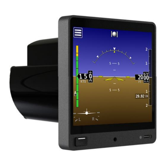
D30
Touchscreen Electronic Flight Display
Installation and Maintenance Manual
Includes Instructions for Continued Airworthiness (ICA)
STC SA02594SE
104003-000
Copyright © 2023 by Dynon Avionics, Inc.
Dynon Avionics grants third parties' permission to print this document
D30
- Installation and Maintenance Manual, Rev A, 6/8/2023
Page | i
Advertisement
Table of Contents

Related Manuals for Dynon D30


Summary of Contents for Dynon D30
- Page 1 Installation and Maintenance Manual Includes Instructions for Continued Airworthiness (ICA) STC SA02594SE 104003-000 Copyright © 2023 by Dynon Avionics, Inc. Dynon Avionics grants third parties' permission to print this document - Installation and Maintenance Manual, Rev A, 6/8/2023 Page | i...
- Page 2 Information in this document is subject to change without notice. Dynon Avionics reserves the right to change or improve its products and to make changes in the content without obligation to notify any person or organization of such changes.
- Page 3 Revision History DYNON SUBMITTAL ACCEPTANCE DESCRIPTION OF CHANGE DATE DATE 6/8/2023 July 10, 2023 Initial Submission ECO 359924 Anchorage ACO - Installation and Maintenance Manual, Rev A, 6/8/2023 Page | iii...
-
Page 4: Table Of Contents
Table of Contents General ....................1-1 Document Control ...................... 1-1 Using this Manual ...................... 1-1 Intended Audience ..................... 1-1 Manual Iconography ....................1-2 Reference Documents ....................1-2 Mechanical Drawings ....................1-2 Product Delivery & Warranty ..................1-2 Product Registration ....................1-2 Installation Record ..................... - Page 5 Cleaning ........................7-2 Backup Battery Test ....................7-2 Backup Battery Replacement ..................7-3 Unit Removal and Replacement ................7-4 Pitot/Static Leakage Tests ..................7-6 Zero-pressure Calibration ..................7-7 Pitch/Roll Angle Check & Adjustment ................ 7-7 Altimeter Function Testing & Altitude Offset .............. 7-8 7.10 System Software Updates ..................
- Page 6 This page intentionally left blank. Page | vi - Installation and Maintenance Manual, Rev A, 6/8/2023...
-
Page 7: General
This document provides installation and configuration information for the Dynon D30 Touchscreen Electronic Flight Display. It also provides Instructions for Continued Airworthiness (ICA) for use by authorized personnel to service and maintain the D30 according to Federal Aviation Regulation (FAR) 14 CFR § 23.1529 and 14 CFR 23 Appendix G. -
Page 8: 1.4 Manual Iconography
Product Delivery & Warranty Upon delivery, visually inspect the D30 and accessories (bracket, fasteners, cable harness) for damage that may have occurred during shipping. If damage has occurred, contact Dynon Technical Support. -
Page 9: Installation Record
The mechanic or facility performing the installation should record where the equipment has been installed in the aircraft. This documentation should be entered into aircraft’s permanent record. Dynon provides a document template to record this information. Download the SkyView HDX Equipment Installation Record document at dynoncertified.com/docs. - Page 10 This page intentionally left blank. Page | 1-4 - Installation and Maintenance Manual, Rev A, 6/8/2023...
-
Page 11: Airworthiness Limitations
Airworthiness Limitations There are no new (or additional) airworthiness limitations associated with the D30 and/or installation. "The Airworthiness Limitations Section is FAA approved and specifies maintenance required under 14 CFR §§ 43.16 and 91.403 of the Federal Aviation Regulations unless an alternative program has been FAA approved."... - Page 12 This page intentionally left blank. Page | 2-2 - Installation and Maintenance Manual, Rev A, 6/8/2023...
-
Page 13: System Overview
For SkyView HDX systems installed under STC SA02594SE, the D30 serves as a standby flight display for SkyView’s Primary Flight Display (PFD). The D30 provides pilots with immediate Primary Flight Information (PFI) in case of a SkyView HDX system failure. It also allows pilots to cross-compare the presented PFI to ensure data integrity. -
Page 14: Basic Controls
Basic Controls Operating the D30 is intuitive for people familiar with flight instrumentation. Basic operation happens via touching the actual indicators on the screen or the menu icon in the upper left corner of screen. The front bezel has an ON/OFF button (i.e., Bezel Button) and a USB-C port. -
Page 15: System Operation
System Operation No special operating procedures are required for using the D30. Operating limitations for the D30 are listed in the 104004-000 D30 Airplane Flight Manual Supplement document at dynoncertified.com/docs. 3.3.1 Flight Indications The D30 provides the flight indications listed below. See... - Page 16 2. If power is applied and unit does not start-up, then press and hold bezel button for two seconds. Unit will start-up. Altitude is not displayed until 30 seconds after start-up. If the D30 senses an airspeed or altimeter setting adjustment, then altitude is immediately displayed.
-
Page 17: Certified Installation Compliance
FAA Form 337 Major Repair & Alteration (Airframe, Powerplant, Propeller, or Appliance). The form must include the following: • Description of the D30 installation. • Appropriately approved or acceptable data that demonstrates compliance. Refer to AC 43.9-1G - Instructions for Completion of FAA Form 337 for additional information. - Page 18 This page intentionally left blank. Page | 4-2 - Installation and Maintenance Manual, Rev A, 6/8/2023...
-
Page 19: Installation
• A small relief must be cut at the bottom of the hole in the instrument panel (see Figure • If retrofitting an EFIS-D10A with a D30, the holes drilled in the instrument panel for the EFIS-D10A can be reused for the D30's bracket (see Figure •... - Page 20 Figure 3: Volume Requirements To mount the D30 to an instrument panel: 1. If needed, use Figure 4 as a guide to mark and drill holes in instrument panel for mount bracket attachment. 2. Cut small relief at bottom of instrument hole (see...
- Page 21 Figure 4: Mounting Dimensions - Installation and Maintenance Manual, Rev A, 6/8/2023 Page | 5-3...
- Page 22 Figure 5: Instrument Panel Installation Page | 5-4 - Installation and Maintenance Manual, Rev A, 6/8/2023...
- Page 23 5.1.1 Replacement Hardware If the provided mounting hardware is lost or damage, replace with the hardware is listed below. Table 1: Replacement Hardware DYNON P/N HARDWARE DESCRITION 100980-001 PHIL SCREW 100 DEG, #6-32, 3/8" L, STAINLESS - Installation and Maintenance Manual, Rev A, 6/8/2023...
-
Page 24: Pitot And Static Connection
Pitot and Static Connection The pitot and static ports on the back of the D30 are equipped with 1/8" NPT female fittings. Installers need to source 1/8" NPT male tube adapters and T-connectors for connection to existing pneumatic tubes. To attach pneumatic tubes to the D30: 1. -
Page 25: Electrical Installation
Electrical Installation The D30 is shipped with D25 female wire harness that plugs into the mating D25 male connector on the back of the unit (see Figure 8). The wire harness has designated wires for connection to airplane power and ground. - Page 26 5.3.1 Power and Ground Connection The D30 is compatible with 14V and 28V electrical systems and requires a power supply of 10– 30V DC. Power input to the D30 must be protected with at least an aviation-grade 3A circuit breaker or replaceable fuse.
-
Page 27: Configuration
3-second countdown timer. After countdown, unit will shut-down. 5.4.2 Setup Menu Access Installers will need to enter the D30's Setup Menu to perform the initial setup configuration tasks. To enter the D30 Setup Menu: 1. Make sure power is not applied to unit. - Page 28 Installers need to configure the system settings per installation, airplane limitations, and user preference. To configure the D30 system settings: 1. Enter Setup Menu (see Section 5.4.2), and then select Settings. 2. Refer to aircraft's POH and configure system settings. See...
- Page 29 5.4.4 Pitot/Static Leakage Tests After configuring the D30, installers need to test the pitot and static systems for leaks (see Section for instructions). 5.4.5 Zero-pressure Calibration After configuring the D30, installers need to perform the zero-pressure calibration to calibrate airspeed (see Section for instructions).
- Page 30 This page intentionally left blank. Page | 5-12 - Installation and Maintenance Manual, Rev A, 6/8/2023...
-
Page 31: Troubleshooting
This section provides information and procedures for troubleshooting issues with the Dynon D30. Self-Diagnostics The D30 includes limited self-diagnostic capability. If a fault or other condition is detected, a message and/or icon is displayed on the screen. The following provides a possible cause and recommended action for each message. - Page 32 MESSAGE / ICON CAUSE RECOMMENDED ACTION The D30 has detected an internal issue in its firmware or calibration tables. Contact Dynon Technical Support. The internal ADAHRS sensors are malfunctioning. DO NOT fly airplane! Unit Does Not Start-up If unit does not start-up, thoroughly check electrical connections, and retry. If unit still does not start-up, contact Dynon Technical Support.
-
Page 33: Maintenance
Maintenance This section provides information and procedures for maintaining the Dynon D30. Periodic Maintenance Table 4 for maintenance tasks that must be performed routinely. Table 5: Periodic Maintenance TASK FREQUENCY DESCRIPTION / PROCEDURE Backup Battery Test Once Every 12 See Section 7.3. -
Page 34: Cleaning
EFIS devices effectively and without damage. The D30 screen and bezel screen can also be cleaned with a soft cotton cloth dampened with clean water. Avoid using harsh cleaning agents. Take care to not scratch surface of display. -
Page 35: Backup Battery Replacement
Backup Battery Replacement If the backup battery needs replacement, it can be replaced in the field. Replacement batteries (Dynon P/N 504103-000) are available from Dynon Avionics or an authorized dealer. To replace the D30 backup battery: 1. Remove unit per instructions in Section 7.5. -
Page 36: Unit Removal And Replacement
Unit Removal and Replacement This section provides procedures for removing and replacing the D30 with and without electrical and pneumatic disconnection. To remove and replace the D30 without disconnection: 1. Make sure airplane power is disconnected. 2. Use 3/32" hex wrench to loosen retaining screw that secures unit to mount bracket (see Figure 11). - Page 37 12. Unplug and connect pitot and static tubes to corresponding tube adapters on back of unit. 13. Plug harness connector into mating connector on back of unit (see Figure 12), and then hand-tighten retention screws to secure. 14. Carefully slide unit into instrument panel. 15.
-
Page 38: Pitot/Static Leakage Tests
D30. When performing the Pitot/Static Leakage Test, put the D30 into Pitot Static Test Mode. Not doing so can corrupt the D30’s internal calibrations. -
Page 39: Zero-Pressure Calibration
Zero-pressure Calibration This calibration samples pitot and static pressures. This calibration needs to be performed during initial setup to calibrate airspeed, and as needed if airspeed indicator appears incorrect. This calibration should be performed in a windless environment to provide the best possible Indicated Airspeed (IAS) readings at very low airspeeds. -
Page 40: Altimeter Function Testing & Altitude Offset
Altimeter Function Testing & Altitude Offset The D30’s altimeter function must be tested in accordance with 14 CFR, Part 43, Appendix E by a certified technician or facility. When performing the Altimeter Function Test, put the D30 into Pitot Static Test Mode. -
Page 41: 7.10 System Software Updates
USB drive or will not be recognizable by the D30. To update system software: 1. While D30 is OFF, use a USB-C adapter to insert USB drive into USB-C port on D30 bezel. 2. Turn D30 ON and wait, and then follow on-screen instructions.
Need help?
Do you have a question about the D30 and is the answer not in the manual?
Questions and answers