Table of Contents
Advertisement
Quick Links
Advertisement
Table of Contents

Related Manuals for Mutec REF10 SE120


Summary of Contents for Mutec REF10 SE120
- Page 1 Manual REF10 REF10 SE120...
-
Page 3: Table Of Contents
Product Registration for Warranty and Support Social Media Installation Shipping Contents Placing the Device Interface Connections Control Elements and Terminals Front Panel Rear Panel Operation General System Operation Recommendations for REF10 and REF10 SE120 Applications Using the REF10 or REF10 SE120 With Other Products 12... -
Page 4: Precautions
If the unit is damaged, please do NOT return This symbol, a flash of lightning inside a triangle, it to MUTEC GmbH, but notify your dealer and the shipping alerts you to the presence of non-insulated dan- company immediately Otherwise, any liability claims will not... -
Page 5: Warranty Regulations
To obtain warranty service, the customer must call or write §3 Warranty Regulations to MUTEC GmbH before returning the unit All inquiries must be accompanied by a problem description and the original The return of the completed registration card, or online regis- buyer’s invoice Devices shipped to MUTEC GmbH for repair... -
Page 6: Introduction
In contrast to so-called »atomic clocks«, clocks based on a ru- • Provides simultaneous reference outputs with 50 and 75 bidium or cesium normal, the REF10 as well as the REF10 SE120 Ω impedance for maximum compatibility with clocks and are engineered around MUTEC's handcrafted, oven-controlled... -
Page 7: Matching Mutec Products
Accessories • MUTEC's PRIME SELECT line of 75 Ohms audio clock cab- les in various lengths, exclusively approved by the REF10, respectivels REF10 SE120 developer Ask your retailer for further details! •... -
Page 8: Installation
We recommend double-checking the operating manual of any device that you are planning the REF10, respectively REF10 SE120 to be connected to A mis- matched termination of the system will cause losses in signal quality and clock precision! - Page 9 Consequently and considering that the REF10, respectively REF10 SE120 provides a total of eight clock outputs we advise against daisy-chaining 10 MHz clock signals Any device that is supposed to be clocked by the REF10, res-...
-
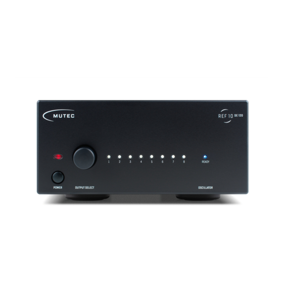
Page 10: Control Elements And Terminals
REF 10 Control Elements and Terminals (equal for REF10 and REF10 SE120) Front Panel Rear Panel 1) »POWER« 1) »50 Ω, Outputs 1 – 2« This red LED illuminates when the device has been powered These two clock outputs are equipped with a 50 Ω terminati- up First engage the rear panel power switch next to the mains on Use only BNC cables with the appropriate 50 Ω... -
Page 11: Operation
These are available from various retailers and can be used The last setting of the REF10, respectively REF10 SE120 will be regardless of the termination impedance of the REF10's, stored and preserved after the the device has been powered... -
Page 12: Applications
The simplest possible application for the REF 10, respectively REF10 SE120 would look like this: Thanks to a total of eight clock outputs on the REF10, respectively REF10 SE120 any 10 MHz compatible device in a setup can and should receive its own dedicated clock supply We strongly advise against daisy-chaining multiple devices using so-called BNC tee adapters (more about this on page 9) Particularly the combination of the REF10 or REF10 SE120 with MUTEC’s own MC3+ and MC3+USB Smart Clocks offers exciting... -
Page 13: 10 Mhz Compatible Products
This particular system can be enhanced by the REF 10, respectively REF10 SE120 in up to three places, depending on how many of the digital devices offer a 10 MHz compatible input In the best possible case, all of the digital sources (e g Blue-ray player,... - Page 14 Audio/Video Clock Generator Disclaimer: Compatibility of the REF 10, respectively REF10 SE120 with the above listed products is assumed based on the specifications published by the respective manufacturers and subject to change MUTEC is not liable for compatibility issues with third-party products operating outside of industry standards...
- Page 15 Network Switch Disclaimer: Compatibility of the REF 10 , respectively REF10 SE120 with the above listed products is assumed based on the specifications published by the respective manufacturers and subject to change MUTEC is not liable for compatibility issues with third-party products operating outside of industry standards...
-
Page 16: Appendix
The respective line voltage »110-120 REF10: 1 × 10 V« or »220-240 V« is printed above the right triangle If this REF10 SE120: 2 5 × 10 setting should not be appropriate for your power grid, the fuse •... - Page 17 Mechanical Details: • Enclosure size/material/color: 196 x 84 x 300 mm (W x H x D, without connectors and case feet), 1,5mm steel, black Phase noise measured at REF10 SE120's outputs (!): powder-coated • 1 Hz: ≤ -120 dB/c •...
Need help?
Do you have a question about the REF10 SE120 and is the answer not in the manual?
Questions and answers