
Subscribe to Our Youtube Channel
Related Manuals for Rosco SAFE -T-SCOPE STSM270


Summary of Contents for Rosco SAFE -T-SCOPE STSM270
- Page 1 SAFE -T-SCOPE ® B A C K U P C A M E R A S Y S T E M S STSM270 7"HD LCD 4 CHANNEL MONITOR INSTALLATION/ USER MANUAL...
-
Page 2: Table Of Contents
Appendix ............15-20 STSM270 SAFE-T-SCOPE 7" HD LCD 4 CHANNEL MONITOR KIT ® Rosco Vision Systems introduces a revolutionary new camera system for commercial vehicles. The new Safe-T-Scope camera system utilizes a 7'' inch monitor to display a 800*480 LCD ®... -
Page 3: Component List And Description
STSM270 COMPONENT LIST AND DESCRIPTION PART NO. DESCRIPTION 7'' HD LCD 4 Channel Monitor STSM270MO Power Harness equipped with 24 Pin Connector, 4 x 4 Pin Camera Inputs & 4 Pin Video Output STSM270PHAR Monitor Sun Shield BAS4515 Washer, use only with Thumb Screw & WAS2221 U-Bracket, not needed when sun shield is used... -
Page 4: Monitor Installation
Safe-T-Scope ® 7" HD LCD 4 CHANNEL MONITOR KIT MONITOR INSTALLATION Find a mounting location inside the vehicle cabin that is convenient to the driver (e.g. center of the dashboard, above the windshield on the ceiling, near the rear view mirror etc). Installer needs to ensure he/she can drill a hole for the 24 pin connector, and that he/she can stow the power harness under a surface near the monitor (under the dash, headliner,etc). - Page 5 STSM270 MONITOR INSTALLATION DIFFERENT CONFIGURATIONS OF MONITOR INSTALLATION • Mounting Option 1: Duck Foot Mount Monitor along with optional sun- Monitor with the Duck Foot Mount fig. 2 fig. 1 shade kit & Duck Foot Mount • Mounting Option 2: U Bracket Mount Monitor with U Bracket Mount Monitor along with optional sun- fig.
-
Page 6: Power Harness Installation
Safe-T-Scope ® 7" HD LCD 4 CHANNEL MONITOR KIT POWER HARNESS INSTALLATION • Once the monitor is mounted, if necessary, drill a hole on the monitor mounting surface near the monitor in which to pass through the monitor cable and 24-pin connector. The hole should be no larger than 1"... -
Page 7: Wiring Diagram
STSM270 STSM270 Wiring Diagram MONITOR SUN SHIELD U-BRACKET (Mounting Options 2 of 2) 7" QUAD SPLIT MONITOR DUCK-FOOT MOUNT (Mounting Options 1 of 2) POWER HARNESS CAMERA 1 CAMERA 2 CAMERA 3 GREEN: TRIGGER 1 CAMERA 4 WHITE: TRIGGER 2 VIDEO/AUDIO OUTPUT BLUE: TRIGGER 3 BROWN: TRIGGER 4... -
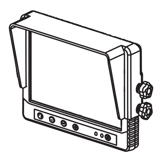
Page 8: Monitor Functions And Operations
Safe-T-Scope ® 7" HD LCD 4 CHANNEL MONITOR KIT MONITOR FUNCTIONS AND OPERATIONS NOTE: The monitor buttons do not function while the vehicle is in reverse. It is recommended that the buttons are ONLY used in park/neutral. POWER ON/OFF Turns the LCD on or off. The monitor, however, is always fully on and functional when receiving power, whether or not the power button is used. -
Page 9: Available Split Screens And Camera Views
STSM270 AVAILABLE SPLIT SCREENS AND CAMERA VIEWS • The below views can be accessed/triggered by the methods below: • Pressing the "CAM" button for manual access • Via triggering using the assignments on the "TRIGGER" monitor menu page. (Manual page 10) •... -
Page 10: Monitor Settings And Menus
Safe-T-Scope 7" HD LCD 4 CHANNEL MONITOR KIT ® MONITOR SETTINGS AND MENU NOTE: Press MENU button to enter the menu and "+" & "-" button to change pages. The menu cannot be accessed when any trigger is activated. Volume can still be adjusted with +/- if triggers are activated. - Page 11 STSM270 MONITOR SETTINGS AND MENU NOTE: Press MENU button to enter the menu and "+" & "-" button to change pages. The menu cannot be accessed when any trigger is activated. Volume can still be adjusted with +/- if triggers are activated. The menu is closed after 10 sec. without any operation.
- Page 12 Safe-T-Scope ® 7" HD LCD 4 CHANNEL MONITOR KIT MONITOR SETTINGS AND MENU NOTE: Press MENU button to enter the menu and "+" & "-" button to change pages. The menu cannot be accessed when any trigger is activated. Volume can still be adjusted with +/- if triggers are activated.
- Page 13 STSM270 MONITOR SETTINGS AND MENU NOTE: Press MENU button to enter the menu and "+" & "-" button to change pages. The menu cannot be accessed when any trigger is activated. Volume can still be adjusted with +/- if triggers are activated. The menu is closed after 10 sec. without any operation.
-
Page 14: Video/Audio Output
The yellow colored 4 PIN FEMALE in the Power Harness cable of Monitor can be connected to a DV440 (Rosco Product) or to an auxiliary display. See schematic diagram example below. VIDEO/AUDIO OUTPUT AUX 1... -
Page 15: Appendix
4 cameras. These cameras can be installed at the rear of the vehicle, left/right side of the vehicle or any other location according to user's wish. An example of camera installation is given here using the STSC101 Rosco Backup Camera. INSTALL MOUNTING BRACKET •... - Page 16 Safe-T-Scope 7" HD LCD 4 CHANNEL MONITOR KIT ® APPENDIX 1.2 CAMERA WIRING EXAMPLE STSC101A CAMERA (AVAILABLE FOR PURCHASE SEPARATELY OR WITH STSK7165B KIT) 4 PIN FEMALE CONNECTOR 4 PIN MALE CONNECTOR STSH341 4-PIN CAMERA EXTENSION CABLE 4 PIN FEMALE CONNECT TO THE MONITOR POWER HARNESS...
- Page 17 STSM270 APPENDIX 1.3 Example monitor application: STSK7165B Kit. STSM270 SAFE-T-SCOPE, 7'' HD LCD 4-CHANNEL MONITOR KIT STC101A CAMERA STSH341 EXTENSION HARNESS GREEN: TRIGGER 1 WHITE: TRIGGER 2 BLUE: TRIGGER 3 VIDEO OUT TO DV440 VIDEO RECORDER OR BROWN: TRIGGER 4 AUXILIARY MONITOR MINI/ATM 2A BLADE FUSE...
- Page 18 2.1 Connection With Vehicle Infotainment Safe-T-Scope 7" 4 Channel Monitor is compatible with most vehicle infotainment systems as long as the vehicle provides RCA connectivity. Using the proper Rosco adapter harnesses, video can be sent to/from the Rosco monitor and vehicle infotainment system..
- Page 19 STSM270 APPENDIX STSM270 Technical specification PARAMETER VALUE Function 7" Quad Split TV System NTSC Resolution 800*480 Brightness ≥500cd/m^2 Video Output 1Vp-p ±.2Vpp 75ohm Power Supply 10~36 VDC Power Consumption ≤8 W Audio Out Operating Current 600mA Standby Current ≤ 400mA Day/Night Mode Auto Vibration...
- Page 20 A CENTURY OF AUTOMOTIVE VISION SAFETY 90-21 144th Place, Jamaica, New York 11435 TEL (800) 227-2095 • FAX (718) 297-0323 techsupport@roscovision.com www.roscomirrors.com www.roscovision.com Lit P/N: MNLSTSM270 Lit. Revision: 1.4 Lit. Revision Date: 06/17/2021...
Need help?
Do you have a question about the SAFE -T-SCOPE STSM270 and is the answer not in the manual?
Questions and answers
How can I rotate the camera view? 2 of my cameras are sideways.