Table of Contents
Advertisement
Quick Links
Advertisement
Table of Contents

Related Manuals for MasterPower OMEGA 2.2KW


Summary of Contents for MasterPower OMEGA 2.2KW
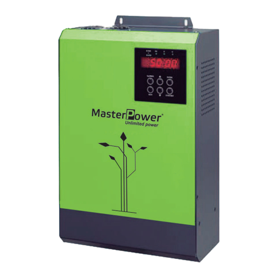
- Page 1 User Manual OMEGA 2.2KW/7.5KW/11KW Solar Inverter for Water Pump Version: 1.8...
-
Page 2: Table Of Contents
Table Of Contents ABOUT THIS MANUAL ............................1 Purpose ................................1 Scope ................................1 SAFETY INSTRUCTIONS ........................... 1 Inspection ................................. 1 Installation ................................ 1 Operation ................................. 2 Maintenance ..............................2 INTRODUCTION ..............................3 Features ................................3 Basic System Architecture ..........................3 Product Overview ............................. -
Page 3: About This Manual
ABOUT THIS MANUAL Purpose This manual describes the assembly, installation, operation and troubleshooting of this unit. Please read this manual carefully before installations and operations. Keep this manual for future reference. Scope This manual provides safety and installation guidelines as well as information on tools and wiring. SAFETY INSTRUCTIONS WARNING: This chapter contains important safety and operating instructions. -
Page 4: Operation
Operation 1. Only after wire connection is complete and put cover back to the inverter, it’s ok to do commissioning. Otherwise, it will cause electric shock 2. If sunlight is sufficient but little water is pumped, maybe the wires on motor connection are reversely connected. -
Page 5: Introduction
INTRODUCTION Interest in renewable energy has increased over the past few years due to solar power becoming more cost effective and eco-friendly. This is a solar inverter which allows power to be switched from the DC power obtained from solar panels to the AC power needed to control the pump. With the renewable solar inverter, pumps can adapt to solar power sources rather than traditional electrical supplies or generators. -
Page 6: Product Overview
Product Overview 1. PV input 2. AC output 3. RS-485 communication port 4. RS-232 communication port 5. Signal control slot 6. Display screen (Refer to Operation and Display Panel for the details) 7. LED indicators (Refer to Operation and Display Panel for the details) 8. -
Page 7: Installation
INSTALLATION Unpacking and Inspection Before installation, please inspect the unit. Be sure that nothing inside the package is damaged. You should have received the following items inside of package: The unit x 1 User manual x 1 RJ45 cable x 1 ... -
Page 8: Pv Connection
Install the unit by screwing four screws. It’s Drill four holes in the marked locations with four recommended to use M5 screws. screws. PV Connection CAUTION: Before connecting to PV modules, please install separately a DC circuit breaker between inverter C8A/2P/1000VDC/25KA for 2.2KW, and PV modules. -
Page 9: Ac Output (Motor) Connection
PV Module Selection: When selecting proper PV modules, please be sure to consider below parameters: 1. Open circuit Voltage (Voc) of PV modules not exceeds max. DC voltage (800VDC). 2. Accumulated voltage of connected PV panels should be close to 560V for inverter with 380V output voltage. To calculate PV module numbers in series (N) and in parallel (M), please follow below formula: Imp>Po/(Kvo x 0.9 x M) ... -
Page 10: Final Assembly
NOTE: To reverse the direction of motor rotation, reverse any two wires. Black (BLK) Red (RED) Yellow (YEL) Ground (GND) International Gray (GRY) Black (BLK) Brown (BRN) Ground (GND) International standards for motor lead wire 3. Make sure the wires are securely connected. Final Assembly After connecting all wirings, please put bottom cover back by screwing two screws as shown below. -
Page 11: Control Signal Connection (Optional)
Control Signal Connection (Optional) There are 7 ports in control signal connection. 2-port on the right side is to power supply for remote panel. 5-port on the left side is to detect water level to prevent water pump from dry running and water tank from overflow/underflow. -
Page 12: Commissioning
Remote float switch (2): It’s to prevent the water pump dry running by connecting to remote float switch. The length of connecting wire should not longer than 50m. If the water level is normal in the well, COM1 and DI3 (S3) is kept in normal close status. -
Page 13: Operation
OPERATION Power ON/OFF Once the unit has been properly installed, simply press “RUN” button (located on the button area) to turn on the unit. Operation and Display Panel The operation and display panel, shown in below chart, is on the top case of the inverter. It includes four indicators, six function buttons and a display screen, indicating the operating status and input/output power information. -
Page 14: Parameter Setting
Function Buttons Function Button Description ESC/PROG To enter or exit setting mode. ENTER To confirm the selection/value in setting mode. To turn on the unit, press this button for at least 1 second. To turn off the unit, press this button for at least 1 second. ... - Page 15 Parameter setting procedure for water pump Operation steps Screen Display 1. Press “ESC/PROG” button for 500ms. Then, it will display “P0” in display screen. 2. Press “ENTER” button for 500ms, display screen will show as in the right chart. 3. Press “ENTER” button again to start to set up rated power of the water pump.
- Page 16 7. Press “ENTER” button to be able to set up nominal voltage of the water pump. Press “ENTER” and “DOWN” buttons at the same time to switch cursor. Then, press “UP” or “DOWN” button to change value for nominal voltage. Until it shows correct nominal voltage, please press “ENTER”...
- Page 17 Parameter Setting Table 〇: This parameter can be modified no matter the inverter is in operation or off status. ◎: This parameter can be modified only when inverter is turned off and it shows 0.00 Hz in display screen. Program # Description Setting Range Unit...
- Page 18 Program # Description Setting Range Unit Default Value Note P3 Protection setting for the inverter of the water pump Sleep mode while PV P3.00 10-3600 〇 energy is weak Sleep mode P3.01 10-7200 1200 〇 running Allow pumping P3.02 1-3600 〇...
-
Page 19: Fault And Warning Code
Fault and Warning Code All fault and warning codes can be reset by pressing “RST” button except for A07 and A11. When faults or warning occur, press “RST” button and the inverter will enter standby mode. Please press “RUN” button to turn on the inverter for operation again. -
Page 20: Warning Reference Codes
Warning Reference Codes Warning code Warning type Possible Cause PV input voltage is too low. 1. PV input voltage is too low. 2. Sunlight is too weak. Weak sunlight Sunlight is too weak Dry running 1. Water level in the well is low. 2. -
Page 21: Specifications
SPECIFICATIONS MODEL 2.2KW 7.5KW 11KW Maximum PV Array Power 3500 W 12000 W 17600 W Rated Output Power 2200 W 7500 W 11000 W PV INPUT (DC) Nominal DC Voltage / Maximum 540 VDC / 800 VDC DC Voltage Start-up Voltage 250 VDC MPPT Voltage Range 250 VDC ~ 780VDC...
Need help?
Do you have a question about the OMEGA 2.2KW and is the answer not in the manual?
Questions and answers