Table of Contents
Advertisement
Quick Links
Advertisement
Table of Contents

Related Manuals for MasterPower OMEGA LV Series


Summary of Contents for MasterPower OMEGA LV Series
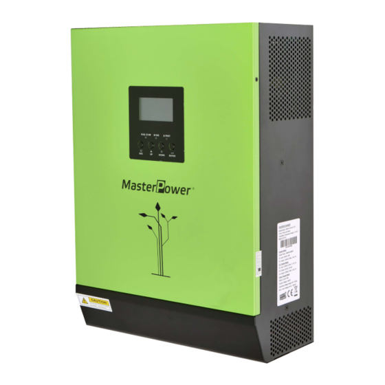
- Page 1 User Manual LV 3KVA-24V INVERTER / CHARGER Version: 1.3...
-
Page 2: Table Of Contents
Table Of Contents ABOUT THIS MANUAL ............................1 Purpose ................................1 Scope ................................1 SAFETY INSTRUCTIONS ........................... 1 INTRODUCTION ..............................2 Product Overview ............................. 3 INSTALLATION ..............................4 Unpacking and Inspection..........................4 Preparation ..............................4 Mounting the Unit ............................. 4 Battery Connection ............................ -
Page 3: About This Manual
ABOUT THIS MANUAL Purpose This manual describes the assembly, installation, operation and troubleshooting of this unit. Please read this manual carefully before installations and operations. Keep this manual for future reference. Scope This manual provides safety and installation guidelines as well as information on tools and wiring. SAFETY INSTRUCTIONS WARNING: This chapter contains important safety and operating instructions. -
Page 4: Introduction
INTRODUCTION This hybrid PV inverter can provide power to connected loads by utilizing PV power, utility power and battery power. Figure 1 Basic hybrid PV System Overview Depending on different power situations, this hybrid inverter is designed to generate continuous power from PV solar modules (solar panels), battery, and the utility. -
Page 5: Product Overview
Product Overview 1KW/2KW 2.4KW/3KW/4KW NOTE: For parallel model installation and operation, please check separate parallel installation guide for the details. LCD display 9. PV connectors Status indicator 10. Battery connectors Charging indicator 11. Circuit breaker Fault indicator 12. Parallel communication cable Function buttons 13. -
Page 6: Installation
INSTALLATION Unpacking and Inspection Before installation, please inspect the unit. Be sure that nothing inside the package is damaged. You should have received the following items inside of package: The unit x 1, User manual x 1, Communication cable x 1, Software CD x 1 Preparation Before connecting all wirings, please take off bottom cover by removing two screws as shown below. -
Page 7: Battery Connection
Battery Connection CAUTION: For safety operation and regulation compliance, it’s requested to install a separate DC over-current protector or disconnect device between battery and inverter. It may not be requested to have a disconnect device in some applications, however, it’s still requested to have over-current protection installed. Please refer to typical amperage in below table as required fuse or breaker size. -
Page 8: Ac Input/Output Connection
AC Input/Output Connection CAUTION!! Before connecting to AC input power source, please install a separate AC breaker between inverter and AC input power source. This will ensure the inverter can be securely disconnected during maintenance and fully protected from over current of AC input. CAUTION!! There are two terminal blocks with “IN”... -
Page 9: Pv Connection
N→Neutral (blue) 5. Make sure the wires are securely connected. CAUTION: Important Be sure to connect AC wires with correct polarity. If L and N wires are connected reversely, it may cause utility short-circuited when these inverters are worked in parallel operation. CAUTION: Appliances such as air conditioner are required at least 2~3 minutes to restart because it’s required to have enough time to balance refrigerant gas inside of circuits. -
Page 10: Communication Connection
connectors. Then, connect positive pole (+) of connection cable to positive pole (+) of PV input connector. Connect negative pole (-) of connection cable to negative pole (-) of PV input connector. Recommended PV module Configuration PV Module Spec. Inverter Model SOLAR INPUT 1 SOLAR INPUT 2 Q'ty of modules... -
Page 11: Operation
OPERATION Power ON/OFF Once the unit has been properly installed and the batteries are connected well, simply press On/Off switch (located on the button of the case) to turn on the unit. Operation and Display Panel The operation and display panel, shown in below chart, is on the front panel of the inverter. It includes three indicators, four function keys and a LCD display, indicating the operating status and input/output power information. -
Page 12: Lcd Display Icons
LCD Display Icons Icon Function Input source information Indicates the AC input Indicates the 1 PV panel input Indicates the 2 PV panel input Left digital display information Indicate input voltage, input frequency, battery voltage, PV1 voltage, PV2 voltage, charger current Middle digital display information Indicates the setting programs. -
Page 13: Lcd Setting
Mode operation information Indicates unit connects to the mains. Indicates unit connects to the 1 PV panel Indicates unit connects to the 2 PV panel Indicates the solar charger is working Indicates the DC/AC inverter circuit is working. Mute operation Indicates unit alarm is disabled. - Page 14 Appliances (default) If selected, acceptable AC input voltage range will be within 90-280VAC for output voltage at 220/230/240Vac or 65-140VAC for output voltage at 101/110/120Vac. AC input voltage range If selected, acceptable AC input voltage range will be within 170-280VAC for output voltage at 220/230/240Vac or 85-140VAC for output voltage at 101/110/120Vac.
- Page 15 Solar energy provides power to the loads as first priority. Overload bypass: Bypass disable Bypass enable When enabled, the unit will (default) transfer line mode overload occurs battery mode. Restart disable Restart enable (default) Auto restart when overload occurs Restart disable Restart enable (default) Auto restart when over...
- Page 16 30A (default) Maximum utility charging current AGM (default) Flooded Battery type User-Defined If “User-Defined” is selected, battery charge voltage and low DC cut-off voltage can be set up in program 17, 18 and 19. 12V model default setting: 14.1V 24V model default setting: 28.2V Bulk charging voltage 48V model default setting: 56.4V (C.V voltage)
- Page 17 24V model default setting: 27.0V 48V model default setting: 54.0V Floating charging voltage If self-defined is selected in program 14, this program can be set up. Setting range is from 12.0V to 15.3V for 12Vdc model, 24.0V to 30.6V for 24Vdc model and 48.0V to 58.4V for 48Vdc model.
- Page 18 12.5V 12.8V Available options for 24V models: 22.0V 22.5V 23.0V (default) 23.5V 24.0V 24.5V 25.0V 25.5V Battery stop discharging voltage when grid is available Available options for 48V models: 44.0V 45.0V 46.0V (default) 47.0V 48.0V 49.0V 50.0V 51.0V Available options for 12V models: Battery fully charged 12.0V Battery stop charging voltage...
- Page 19 12.3V 12.5V 12.8V 13.0V 13.3V 13.5V (default) 13.8V 14.0V 14.3V 14.5V Available options for 24V models: Battery fully charged Battery stop charging voltage when grid is available 24.5V 25.5V 26.5V 27V (default) 27.5V 28.5V...
- Page 20 Available options for 48V models: Battery fully charged 48.0V 49.0V 50.0V 51.0V 52.0V Battery stop charging voltage when grid is available 53.0V 54.0V 55.0V 56.0V 57.0V 58.0V Return to default If selected, no matter how users display screen (default) switch display screen, it will automatically return to default display screen (Input voltage /output voltage) after no button is...
- Page 21 Record enable(default) Record disable Record Fault code AC output mode: This setting is only for the inverter in parallel operation. For the detailed setting, please check section 7 in parallel function chapter. *This setting is only available when the inverter is in standby mode (Switch off).
- Page 22 Germany If selected, acceptable feed-in grid voltage range will be 184~264.5VAC. Acceptable feed-in grid Set country customized frequency range will be regulations 47.5~51.5Hz. (This setting is only available South America If selected, acceptable for 1KW, 2KW, 3KW, 4KW and feed-in grid voltage range will 5KW models) be 184~264.5VAC.
-
Page 23: Display Setting
Display Setting The LCD display information will be switched in turns by pressing “UP” or “DOWN” key. The selectable information is switched as below order: input voltage, input frequency, PV voltage, charging current, battery voltage, output voltage, output frequency, load percentage, load in Watt, load in VA, load in Watt, DC discharging current, main board firmware version and SCC firmware version. - Page 24 Battery voltage and load in VA Battery Voltage=27.0V, load in VA=1.08kVA Battery voltage and load in Watt Battery Voltage=27.0V, load in Watt=1.88kW PV1 voltage and PV1 charger power PV1 Voltage=69V, charging power=1.58kW PV2 voltage and PV2 charger power PV2 Voltage=69V, charging power=1.58kW Charger current and Charging current=30A, discharging current=0A DC discharging current...
- Page 25 PV energy generated today Today energy = 6.3kWh PV energy generated this month This month energy = 358kWh. PV energy generated this year This year energy = 8.32MWh PV energy generated totally Total energy = 13.9MWh Real date Real date Nov 28, 2015. Real time Real time 13:20.
-
Page 26: Operating Mode Description
Main board firmware version Version 00001.00 SCC firmware version Version 00002.00 Operating Mode Description Operating mode Behaviors LCD display Battery is charged by utility. Battery is charged by PV energy. Standby mode Note: *Standby mode: The inverter is not turned on yet but at this time, the inverter can Battery is charged by utility and PV energy. - Page 27 Utility charges battery and provides power to load. Utility and battery power provide power to load. Output power from utility. Charger available PV energy, battery power and utility provide power to load. PV energy and utility charge battery, and utility Line mode provides power to load.
- Page 28 PV energy charges battery and provides power to the load. Battery provides power to the load. No charging. Fault mode Note: No output, no *Fault mode: Errors are caused by inside circuit error charging. or external reasons such as over temperature, output short circuited and so on.
- Page 29 Faults Reference Code Fault Code Fault Event Icon on Fan locked Over temperature Battery voltage is too high Battery voltage is too low Output short circuited Output voltage abnormal Over load time out Bus voltage is too high Bus soft start failed Over current or surge Bus voltage is too low Inverter soft start failed...
-
Page 30: Specifications
SPECIFICATIONS MODEL 2.4KW RATED OUPUT POWER 1000 W 2000 W 3000W 4000W 5000W 2400W PV INPUT (DC) Max. PV Power 1000W 2000W 4000W 4000W 6000W 2000W Max. Array Open Circuit 145 VDC 145 VDC 145 VDC 145 VDC 145 VDC 145 VDC Voltage 30 VDC~115 VDC... -
Page 31: Trouble Shooting
TROUBLE SHOOTING Problem LCD/LED/Buzzer Explanation / Possible cause What to do Unit shuts down LCD/LEDs and buzzer automatically will be active for 3 The battery voltage is too low 1. Re-charge battery. during startup seconds and then (<1.91V/Cell) 2. Replace battery. process. -
Page 32: Parallel Function (Only For 2.4Kw/3Kw/4Kw/5Kw Models)
PARALLEL FUNCTION (only for 2.4KW/3KW/4KW/5KW models) 1. Introduction This inverter can be used in parallel with two different operation modes. 1. Parallel operation in single phase with up to 9 units. The supported maximum output power is 45KW. 2. Maximum nine units work together to support three-phase equipment for 3KW-5KW models or support two-phase equipment for 2.4KW model. - Page 33 Step 3: Remove two screws as below chart and remove 2-pin and 14-pin cables. Take out the board under the communication board. Step 4: Remove two screws as below chart to take out cover of parallel communication. Step 5: Install new parallel board with 2 screws tightly. Step 6: Re-connect 2-pin and 14-pin to original position.
- Page 34 Step 7: Put communication board back to the unit. Step 8: Put wire cover back to the unit. Now the inverter is providing parallel operation function. 4. Mounting the Unit When installing multiple units, please follow below chart. NOTE: For proper air circulation to dissipate heat, allow a clearance of approx. 20 cm to the side and approx. 50 cm above and below the unit.
- Page 35 Recommended AC input and output cable size for each inverter: Model AWG no. Torque 2.4KW 10 AWG 1.4~1.6Nm 12 AWG 1.4~1.6Nm 8 AWG 1.4~1.6Nm 1 x 8 AWG 1.4~1.6Nm You need to connect the cables of each inverter together. Take the battery cables for example: You need to use a connector or bus-bar as a joint to connect the battery cables together, and then connect to the battery terminal.
- Page 36 fault mode. 5-1. Parallel Operation in Single phase Two inverters in parallel: Power Connection Load Communication Connection Three inverters in parallel: Power Connection Load...
- Page 37 Communication Connection Four inverters in parallel: Power Connection Load Communication Connection Five inverters in parallel: Power Connection Load...
- Page 38 Communication Connection Six inverters in parallel: Power Connection Load Communication Connection Seven to nine inverters in parallel: Power Connection Unit 1 Unit 2 Unit 4 Unit 5 Unit 3 Unit 6 Unit 7 Unit 8 Unit 9 Load Communication Connection Seven inverters in parallel ...
- Page 39 Nine inverters in parallel ① ② ③ ④ ⑤ ⑥ ⑦ ⑧ ⑨ 5-2. Support 2-phase equipment (only for 2.4KW model) Two inverters in each phase: Power Connection Load Communication Connection ❶ ❷ Two inverters in one phases and one inverter for the remaining phase: Power Connection Load...
- Page 40 Communication Connection ❶ ❷ ❸ 5-3. Support 3-phase equipment Three inverters in each phase: Power Connection Load Communication Connection ① ② ③ ⑤ ⑥ ⑦ ④ ⑧ ⑨ WARNING: Do not connect the current sharing cable between the inverters which are in different phases. Otherwise, it may damage the inverters.
- Page 41 Communication Connection Seven inverters in one phase and one inverter for the other two phases: Power Connection Load Note: It’s up to customer’s demand to pick 7 inverters on any phase. P1: L1-phase, P2: L2-phase, P3: L3-phase. Communication Connection ① ②...
- Page 42 Four inverters in one phase and one inverter for the other two phases: Power Connection Load Note: It’s up to customer’s demand to pick 4 inverters on any phase. P1: L1-phase, P2: L2-phase, P3: L3-phase. Communication Connection Three inverters in one phase, two inverters in second phase and one inverter for the third phase: Power Connection Load Communication Connection...
- Page 43 Three inverters in one phase and only one inverter for the remaining two phases: Power Connection Load Communication Connection Two inverters in two phases and only one inverter for the remaining phase: Power Connection Load...
- Page 44 Communication Connection Two inverters in one phase and only one inverter for the remaining phases: Power Connection Load Communication Connection...
- Page 45 One inverter in each phase: Power Connection Load Communication Connection WARNING: Do not connect the current sharing cable between the inverters which are in different phases. Otherwise, it may damage the inverters. 6. PV Connection Please refer to user manual of single unit for PV Connection. CAUTION: Each inverter should connect to PV modules separately.
- Page 46 7. LCD Setting and Display Setting Program: Program Description Selectable option Single: When the unit is operated alone, please select “SIG” in program 28. When the units are used in parallel with Parallel: single phase, please select “PAL” in program 28.
- Page 47 When “ALL” is selected, parallel or 3-phase system will continue working according to rule of “solar first” setting only when all of inverters are connected to PV modules. For example, two units are connected in All of Inverters: parallel and set “SOL” in output source priority.
- Page 48 8. Commissioning Parallel in single phase Step 1: Check the following requirements before commissioning: Correct wire connection Ensure all breakers in Line wires of load side are off and each Neutral wires of each unit are connected together. Step 2: Turn on each unit and set “PAL”...
- Page 49 Step 5: If there is no more fault alarm, the system to support 2-phase equipment is completely installed. Step 6: Please switch on all breakers of Line wires in load side. This system will start to provide power to the load.
- Page 50 9. Trouble shooting Situation Fault Solution Fault Event Description Code Restart the inverter. Check if L/N cables are not connected reversely in all inverters. For parallel system in single phase, make sure the sharing are Current feedback into connected in all inverters. the inverter is For supporting three-phase system, make sure the sharing cables are detected.
Need help?
Do you have a question about the OMEGA LV Series and is the answer not in the manual?
Questions and answers