Table of Contents
Advertisement
Available languages
Available languages
Quick Links
Advertisement
Chapters
Table of Contents

Subscribe to Our Youtube Channel
Related Manuals for Wamsler W2-50


Summary of Contents for Wamsler W2-50
- Page 1 Aufstell- und Bedienungsanleitung Instructions for Installation and Use Instructions de montage et d’utilisation Istruzioni per l’installazione e l’uso Kezelési és beállítási útmutató W2-50...
-
Page 2: Vorwort
Vorwort Sehr verehrter Kunde, Wir beglückwünschen Sie zum Erwerb unseres Festbrennstoffherdes. Sie haben die richtige Wahl getroffen. Denn mit diesem Produkte haben Sie die Garantie für Hohe Qualität durch Verwendung bester und bewährter Materialien. Funktionssicherheit durch ausgereifte Technik, die streng nach deutschen bzw. europäischen Normen geprüft ist. -
Page 3: Table Of Contents
Inhaltsverzeichnis Vorwort........................ 2 Inhaltsverzeichnis....................3 1. Installation ...................... 4 1.1 Sicherheitshinweise..................4 1.2 Geräteaufbau ....................6 1.3 Vorschriften ....................7 1.4 Aufstellungsraum..................7 1.5 Verbrennungsluft ..................7 1.6 Sicherheitsabstände..................9 1.7 Schornsteinanschluss ................10 1.8 Wahl der Abgasanschlussrichtung ............10 1.8.1 Obenanschluss .................. -
Page 4: Installation
1. Installation 1.1 Sicherheitshinweise 1. Die Geräte sind nach DIN EN 12815 geprüft (Typenschild). 2. Bei der Aufstellung und dem abgasseitigen Anschluss sind die anwendbaren nationalen und europäischen Normen, örtliche und baurechtliche Vorschriften/Normen (z.B. DIN 18896, DIN 4705, DIN EN 13384, DIN 18160, DIN EN 1856-2, DIN EN 15287 u.a.) sowie feuerpolizeiliche Bestimmungen (z.B. - Page 5 Abgaswege und der Abgasrohre erfolgen. 21. Wenn Ausbesserungen oder Erneuerungen vorgenommen werden müssen, wenden Sie sich bitte rechtzeitig unter Angabe der genauen Art.Nr. und Fert.Nr. an Ihren Fachhändler. Es sind nur Original Wamsler - Ersatzteile zu verwenden. 22. Arbeiten, insbesondere...
-
Page 6: Geräteaufbau
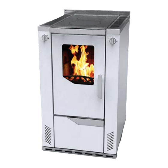
______________________________________________________________________ 1.2 Geräteaufbau W1-50 Legende Primärluftregler Kochplatte Abgasanschlüsse Anheizklappe Schamotteverkleidung im Feuerraum Rost Holzfang (Reling) Seitenwand Aschekasten 10. Sekundärluftregler 11. Brennstoffwagen 12. Sockelrahmen 13. Heiztür Serienzubehör Deckelheber Russkratzer Schürhacken Blinddeckelset Schutzhandschuh Sonderzubehör ISO Panel Anschlussset oben (nicht bei Voll-Ceranplatten möglich) Saugknopf (zu Glaskeramik Einsatz Hot Spots) ______________________________________________________________________... -
Page 7: Vorschriften
1.3 Vorschriften Für die Aufstellung und dem abgasseitigen Anschluss sind die anwendbaren nationalen und europäischen Normen, örtliche und baurechtliche Vorschriften/Normen (z.B. DIN 18896, DIN 4705, DIN EN 13384, DIN 18160, DIN EN 1856-2, DIN EN 15287 u.a.) sowie feuerpolizeiliche Bestimmungen (z.B. FeuVo) zu beachten. Lassen Sie das Gerät nur von einem qualifizierten Fachmann aufstellen und anschließen. - Page 8 Wichtige Hinweise zum Thema raumluftabhängiger bzw. raumluftunabhängiger Betrieb: (gültig für Deutschland. Stand Januar 2013) Punkt 1: Die Herde sind als raumluftabhängige Herde nach DIN EN 12815 geprüft. Die Herde entnehmen die gesamte Verbrennungsluft über den zentralen Luftansaugstutzen aus dem Aufstellraum. An diesem Stutzen kann bauseits eine dichte Luftzuführung angeschlossen werden.
-
Page 9: Sicherheitsabstände
1.6 Sicherheitsabstände Die Sicherheitsabstände von brennbaren Gegenständen und von tragenden Wänden aus Stahlbeton, sowie Stellwänden die aus brennbaren Baustoffen hergestellt, oder mit brennbaren Baustoffen verkleidet sind einzuhalten: Unterhalb der Herdplatte (von Oberkante Herd bis Fußboden) A ≥ 800 mm B ≥ 3 mm* C ≥... -
Page 10: Schornsteinanschluss
1.7 Schornsteinanschluss Der für den Anschluss vorgesehene Schornstein muss bis mind. 400 C belastbar sein. ACHTUNG: Anschluss Gerätes jedem Fall zuständige Bezirksschornsteinfegermeister / Bezirksbeauftragte zu Rate zu ziehen! Verbindungsstücke müssen am Gerät und untereinander fest und dicht verbunden sein. dürfen nicht freien Schornsteinquerschnitt... -
Page 11: Seitenanschluss
1.8.2 Seitenanschluss • hinteren Abgasstutzen (1) durch lockern der Schrauben entfernen • Herdplatte (2) und Durchbrandplatten (3) heraus nehmen • Sturzzugschale (4) vom Rauchgasweg heraus ziehen • Abgasanschluss hinten mit Blinddeckel (5) von Außen verschließen und fest verschrauben • Blinddeckel Innen (6) mit Blinddeckel Außen durch das Schraubenloch und der Schraube (7) verschrauben •... - Page 12 Richtig Falsch mind. 50 cm Querschnittverengung im Kamin durch zu weit eingeschobene Abgasrohre Stau durch sich ge- genseitig behin- mind. 30 cm dernde Abgasströ- Falschluft durch offene Türen an nicht benutzten Feuerstätten Falschluft durch of- fenen Rohranschluß Falschluft durch undichten Rohr- anschluß...
-
Page 13: Brennstoffe / Einstellungen
Nennwärmeleistung heizen. Sollte beim ersten Heizvorgang die max. Temperatur nicht erreicht werden, so können diese Erscheinungen auch später noch auftreten. Maximale Aufgabemengen pro Brennstofffüllung W2-50 3,1 kg (5 - 6 Briketts) bei Nennwärmeleistung Braunkohlebriketts und bei Dauerbrand (andere Einstellung, siehe Tabelle 2) -
Page 14: Bedienung
3. Bedienung 3.1 Bedienungselemente und Einstellungen 3.1.1 Primärluftregulierung Die Verbrennungsgeschwindigkeit und damit die Heizleistung des Herdes werden durch die unter dem Rost einströmende Verbrennungsluft bestimmt. Diese Primärluft wird mit der Leistungsregulierung eingestellt. Geschlossen Scheitholz Braunkohle 3.1.2 Sekundärluftregulierung Der Sekundärluftregler ist auf der Innenseite vom Korpus, hinter der Heiztür. Mit dieser Einstellung wird der Brennstoff gewählt. -
Page 15: Aschekasten
3.1.4 Aschekasten • Der Aschenbehälter befindet sich unter der Feuerstätte. Er muss regelmäßig überprüft und geleert werden. • Das Leeren des Aschenbehälters ist bei kaltem Gerät vorzunehmen. Seien Sie bitte vorsichtig, da noch Glut oder brennende Holzstückchen vorhanden sein können. Bitte beachten Sie, dass keine glühenden Verbrennungsrückstände in die Mülltonne gelangen. -
Page 16: Kochen Und Heizen
Nennwärmeleistung heizen. Sollte beim ersten Heizvorgang die max. Temperatur nicht erreicht werden, so können diese Erscheinungen auch später noch auftreten. Den Brennstoff nicht in den Brennraum einwerfen, sondern einlegen, da sonst die Ausmauerung beschädigt werden kann. Der Herd darf nur mit geschlossener Fülltür (Heiztür) betrieben werden. Diese darf nur zum Anheizen, Nachlegen oder Reinigen des Feuerraums geöffnet werden. -
Page 17: Pflege Und Reinigung
Im Interesse der Luftreinhaltung und dem Ofen sollten die angegebenen max. Brennstoffaufgabemengen nicht überschritten werden, da sonst die Gefahr des Überheizens besteht, was zu Beschädigungen am Gerät führen kann. Beschädigungen solcher Art, unterliegen nicht der Garantiepflicht. Eine reduzierte Heizleistung sollte nur durch Verringerung der Aufgabemenge und nicht durch Reduzierung der Primärluft erfolgen. -
Page 18: Seitliches Schutzgitter
bedürfen deshalb einer regelmäßigen Wartung nach jedem Kochen. Bei jeder Benutzung, die Feuchtigkeit oder Schmutz auf der Platte verursacht hat, sollte gereinigt werden. Man sollte die Herdplatte säubern wenn sie noch lauwarm ist, so kann eventuell vorhandenes Wasser verdunsten und es bilden sich keine Rostflecke. Es ist darauf zu achten, dass bei kaltem Herd kein Wasser zum reinigen benutzt wird. -
Page 19: Störungsursachen, Behebung
3.7 Störungsursachen, Behebung Ihr Herd ist nach den neuesten technischen Erkenntnissen gebaut. Dennoch können Störungen auftreten, die meist ihre Ursache im Schornstein, im Brennstoff oder Abgasrohrsystem haben. Eine kurzzeitige Geruchs- Rauchentwicklung bei der ersten Inbetriebnahme ist normal. Auf eine ausreichende Belüftung des Raumes ist zu achten. -
Page 20: Technische Daten
≤ 40 mg/m³ CO (bezogen auf 13% O ≤ 0,09 % Wirkungsgrad ≥ 77 % 4.2 Maßzeichnungen W2-50 850 (+20) 695 (+20) 900 (+20) 745 (+20) Stellfüße herausschrauben, Herdhöhe von +20 mm möglich Die angeführten Abmessungsangaben sind nur zur Information! Wir behalten uns das Recht von Konstruktionsänderungen vor, falls diese das technische Niveau erhöhen, oder die... -
Page 23: Preface
______________________________________________________________________ Preface Dear Customer, Congratulations on your purchase of our solid fuel stove. You have made a good choice. Because this product guarantees you: • High Quality by using proved materials with top quality. • Safe function thanks to mature technology which has been tested for strict adherence to German and European standards. -
Page 24: Table Of Contents
Table of Contents Preface ......................23 Table of Contents..................... 24 Installation ................... 25 Safety measures ................... 25 Parts ...................... 27 Instructions .................... 28 Surrounding space ................28 Air supply ....................28 Safe distances..................30 Chimney attachment ................31 Choice of flue gas connection placement ..........31 1.8.1 Top connection (Fig. -
Page 25: Installation
______________________________________________________________________ Installation Safety measures The stoves are tested to DIN EN 12815 (see identification plate). For installation and for flue gas connections, the requirements of the Fire Regulations (FeuVO in Germany) apply, as well as local building regulations such as the following technical standards DIN 4705, DIN EN 13384, DIN 18160, DIN EN 1856-2 and DIN EN 15287. - Page 26 18. If repairs or replacements are necessary, please contact your supplier with the necessary article numbers and serial numbers in good time. Only original WAMSLER replacement parts may be used. 19. Work such as installation, setup, commissioning and services, as well as repairs, must only be carried out by qualified personnel (heating system or space heating technicians).
-
Page 27: Parts
______________________________________________________________________ Parts W2-50 Key: Standard accessories: 1. Primary air control - Flue cover 2. Steel plate - Protective gloves 3. Flue gas connections - Lever to lift covers 4. Start damper - Soot scraper 5. Refractory clay layer in fire chamber - Fire iron 6. -
Page 28: Instructions
______________________________________________________________________ Instructions For installation and for connection of flue, the requirements of the Fire Regulations (FeuVO in Germany) apply, as well as local building regulations such as the following technical standards DIN 4705, DIN EN 13384, DIN 18160, DIN EN 1856-2 and DIN EN 15287. In order for the stove to function correctly the chimney to which you want to connect the stove must be in good condition. - Page 29 ______________________________________________________________________ Important NOTES relevant to operation dependent on air supply from room or independent of air supply from room (valid for Germany – as of January 2013): • The stoves have been tested under DIN EN 12815 as stoves relying on air supply from room.
-
Page 30: Safe Distances
______________________________________________________________________ Safe distances The following distances must be respected as safety margins from flammable objects and bearing walls made of reinforced concrete and partition walls made from flammable materials or covered in flammable materials: Beneath the hob plate (from the top of the stove to the floor) A ≥... -
Page 31: Chimney Attachment
Chimney attachment The connection for attaching to the chimney must be able to withstand at least 400°C. PLEASE NOTE: Before connecting the stove the local authority responsible for approving heating systems must be consulted! Connection pieces must be firmly connected to the stove and to each other and must not leak. -
Page 32: Side Connection (Fig. 1)
1.8.2 Side connection (Fig. 1) • Remove the rear flue outlet (1) by loosening the screws. • Remove the cooking plate (2) and the fire bricks (3) • Remove the steel plate (4) in the exhaust • Bolt tight the cover (6) at the inside with the outside cover (7). •... - Page 33 Right Richtig Wrong Falsch min. 50 cm mind. 50 cm Chimney diameter reduced due to flue being inserted too far into Querschnittverengung im Kam in durch zu chimney weit eingeschobene Abgasrohre Blockage due to exhaust gases interfering with each Stau durch sich ge- mind.
-
Page 34: Fuels / Settings
Maximum fuel quantities per load W2-50 3.1 kg (5 - 6 briquettes) at nominal heat load Lignite briquettes 3.1 kg (5 - 6 briquettes) for long term load... -
Page 35: Combustion Airflow Settings
Combustion airflow settings The settings must always be as shown. Combusti Primary Secondary Start damper Fuel airflow airflow setting duration setting setting in hrs Lighting Nominal Firewood approx. 1 heat load Nominal Lignite briquettes approx. 2 heat load Long-term approx. Lignite briquettes heating Not in use: do not add any... -
Page 36: Start Damper
3.1.3 Start damper For lighting the stove the start damper must be open and when cooking or heating it must be closed. 1 - Closed (cooking, heating) 2 - Open PLEASE NOTE: Leaving the start damper open when heating will cause the stove to overheat which will damage the stove and its parts. -
Page 37: Lighting
Lighting The performance control is set depending on the type of fuel as a function of the chimney draught and the desired heating level. With firewood and particularly with softwood, only a limited heating period is possible. Lignite briquettes are much better suited to burning overnight, if they are placed on top of a layer of glowing embers. -
Page 38: Closing Down
The hob plate must not be overheated as this will damage the stove but not help in any way with cooking. Closing down Close the primary air regulator (Table 2). Let the embers burn out and leave the stove to cool down. Once the stove is cold, empty and clean out the fire chamber and ash pan! Notes on heating A properly adjusted secondary air flow ensures that any combustible elements in... -
Page 39: Varnished And Enamel Surfaces
cleaned. By loosening of the cleaning cover (4) the lower part of the flue gas channel around the oven can also be cleaned. After finishing cleaning, the heating and hob plates must be replaced correctly. The cleaning cover (4) under the oven needs to be closed tightly again. PLEASE NOTE: After every period of heating you should check the stove thoroughly. -
Page 40: Side Panel Top
Parts explosion diagram for Chapter 3.6 Care and cleaning: Fig. 4 3.6.5 Side panel top 1. Stainless steel grating, lifting (Figure 5) 2. Pull forward 3. and lifting After disassembling the stainless steel grating, can the underlying hole tray, be cleaned. -
Page 41: Troubleshooting
Troubleshooting Your stove has been built using modern technology. Even so, problems can arise, which may derive from the chimney, the fuel or the flue pipe system. There may briefly be smoke and an unpleasant smell the first time you use the stove: this is normal. Make sure the room is sufficiently well ventilated. -
Page 42: Technical Data
≤ 40 mg/m³ Particles / dust (based on 13% O2) ≤ 0,09 % CO ( based on 13% O2) ≥ 77 % Efficiency Dimensions W2-50 850 (+20) 695 (+20) 900 (+20) 745 (+20) screw feet can raise stove height by +20 mm... - Page 43 Préface Cher client, Nous vous félicitons d’avoir fait l’acquisition de notre cuisinière à combustible solide. Vous avez fait le bon choix. Ce produit vous donne en effet la garantie • d’une qualité élevée obtenue grâce à l’utilisation des matériaux les meilleurs et les mieux éprouvés, •...
- Page 44 Sommaire Installation ................... 45 Consignes de sécurité................45 Structure de l’appareil ................47 Règlements ................... 48 Pièce d’emplacement................48 Air de combustion ................. 48 Distances de sécurité................50 Raccordement à la cheminée ............... 51 Choix de la direction de l’évacuation des fumées......... 52 1.8.1 Raccordement par le haut (figure 1)..........
-
Page 45: Installation
Installation Consignes de sécurité 1. Les appareils ont été contrôlés selon les normes DIN EN 12815 (Plaque signalétique). 2. Pour la mise en place des appareils et le raccordement aux cheminées d’évacuation des gaz, on devra observer les exigences énoncées par les directives concernant les appareils de chauffage (FeuFO en Allemagne) ainsi que les normes DIN 4705, DIN EN 13384, DIN 18160, DIN EN 1856-2 et DIN EN 15287. - Page 46 à temps à votre commerçant spécialisé en lui indiquant exactement le numéro de référence et le numéro de fabrication. On ne peut utiliser que des pièces originales WAMSLER. 19. Les travaux, tels que, en particulier, l’installation, le montage, la première mise en service, les travaux de maintenance ainsi que les réparations ne pourront être...
-
Page 47: Structure De L'appareil
______________________________________________________________________ Structure de l’appareil W2-50 Légende : Accessoires de série : Réglage de l’air primaire - Levier de couvercle Plaque d’acier - Brosse à suie Raccordement pour les gaz d’évacuation - Tisonnier Volet d’allumage - Gants de protection Revêtement réfractaire dans le foyer - Couvercle de sortie de fumée... -
Page 48: Règlements
Règlements Pour la mise en place des appareils et le raccordement aux cheminées d’évacuation des gaz on devra observer les exigences des pays et des régions énoncées par les directives concernant les appareils de chauffage (FeuVO en Allemagne) ainsi que les normes DIN 4705, DIN EN 13384, DIN 18160, DIN EN 1856-2 et DIN EN 15287. - Page 49 Consignes importantes concernant le fonctionnement d’appareils dépendants ou indépendants de l’air ambiant (valable pour l'Allemagne – selon la réactualisation des règlements et directives en la matière de janvier 2005) • Les cuisinières ont été contrôlées selon la norme DIN EN 12815 comme cuisinières dont le fonctionnement dépend de l’air ambiant.
-
Page 50: Distances De Sécurité
Distances de sécurité On devra respecter les distances de sécurité rapport à des objets inflammables aux murs portants en béton armé ainsi que par rapport aux parois en matériaux combustibles ou revêtues de matériaux combustibles : Au-dessous de la plaque de foyer (du bord supérieur de la plaque de foyer au plancher) A ≥... -
Page 51: Raccordement À La Cheminée
Raccordement à la cheminée La cheminée prévue pour le branchement devra résister au minimum à une température de 400 °C. TTENTION Avant de raccorder l’appareil, il est nécessaire, dans tous les cas de consulter le ramoneur responsable de la circonscription ! Les éléments de la conduite d’évacuation doivent être bien fixés les uns aux autres. -
Page 52: Choix De La Direction De L'évacuation Des Fumées
Choix de la direction de l’évacuation des fumées La buse d’évacuation des fumées est montée, en série, sur l’arrière de l’appareil. Si l’on choisit de raccorder la cuisinière à la cheminée par le haut ou par les côtés, l’orifice d’évacuation non utilisé devra être fermé. 1.8.1 Raccordement par le haut (figure 1) •... - Page 53 Figure 1...
- Page 54 Juste Richtig Falsch Faux min. 50 cm mind. 50 cm Rétrécissement de la section Querschnittverengung dans la cheminée parce que le im Kam in durch zu tuyau pénètre trop dans le weit eingeschobene conduit Abgasrohre Retenue parce que les deux courants de gaz Stau durch sich ge- se freinent genseitig...
-
Page 55: Combustibles / Réglages
à l’avenir. Quantité maximale de combustible à ne pas dépasser lors du chargement W2-50 3,1 kg (5 - 6 briquettes de lignite) pour la puissance Briquettes de calorifique nominale. -
Page 56: Réglage De L'air De Combustion
Réglage de l'air de combustion Les réglages doivent toujours être sur la position des marques placées sur l’appareil Durée de Réglage de l’air Position du Position de l’air Combustible combustion primaire volet d’allumage secondaire en heures Chauffer Bûches 1 env. Briquettes de lignite 2 env. -
Page 57: Volet D'allumage
3.1.3 Volet d’allumage Le volet d’allumage doit être ouvert pour l'allumage mais doit être fermé pendant le chauffage et la cuisson. Fermé (cuisson, cuire au four, rôtir, chauffer) Ouverte TTENTION Si le volet d’allumage reste constamment ouvert pendant le fonctionnement du chauffage, la cuisinière risque de surchauffer et des pièces peuvent être endommagées. -
Page 58: Allumer
Allumer Tout d’abord, on réglera la puissance en tenant compte du type de combustible et de la puissance de chauffage souhaitée. Les bûches, et plus particulièrement le bois tendre ne permettent qu’un feu continu limité. Les briquettes de lignites sont particulièrement bien adaptées au feu continu nocturne si elles sont placées sur une bonne couche de braises. -
Page 59: Chauffage Et Cuisson
Chauffage et cuisson Si la cuisinière est utilisée pour le chauffage ou pour la cuisson, le volet d’allumage doit être fermé. Pour une cuisson optimale, nous recommandons de n’utiliser que des casseroles à fond plat. La zone la plus chaude de la cuisinière se trouve au centre de anneaux qui est aussi, en même temps, la meilleure zone pour réchauffer une casserole rapidement. -
Page 60: Nettoyage, Entretien Et Maintenance
seulement réduire la quantité de combustible au moment du chargement, il ne faut pas réduire l’amenée d’air primaire. Nettoyage, entretien et maintenance 3.6.1 Appareil (figure 4) Après avoir ouvert la porte de chargement, il est nécessaire de nettoyer la grille de tous les restes à... -
Page 61: Plaque D'acier
de la plaque de vitrocéramique et facile le nettoyage lorsque ces soins ont lieu régulièrement. 3.6.4 Plaque d’acier Les pièces en plaques d’acier doivent être traitées avec un produit de nettoyage pour plaque d’acier sans acide alors qu’elles sont encore tièdes. On procédera à ce nettoyage que lorsque la cuisinière est froide. -
Page 62: Inoxydable Caillebotis
3.6.5 Inoxydable caillebotis 1. inoxydable caillebotis en acier, de levage (Figure 5) 2. Tirer vers l'avant 3. levage et Après démontage de la grille en acier inoxydable, peut le plateau de trou sous- jacente, être nettoyé. Remontage a lieu dans l'ordre inverse. Fig 5. -
Page 63: Causes De Perturbations, Solutions
Causes de perturbations, solutions Votre cuisinière est construite selon l’état des techniques le plus récent en la matière. Toutefois, des perturbations peuvent être provoquées par la cheminée, le combustible ou le système de tuyaux d’évacuation de gaz. Des dégagements de fumées et d’odeurs sont normaux à... -
Page 64: Caractéristiques Techniques
≤ 40 mg/m³ CO (pour 13 % de O ≤ 0,09 % Rendement d'exploitation ≥ 77 % Dessins côtés W2-50 850 (+20) 695 (+20) 900 (+20) 745 (+20) Retirer les pieds réglables il est possible d’augmenter la hauteur de la cuisinière de 20 cm. -
Page 65: Indice Premessa
Premessa Gentilissimo Cliente, ci complimentiamo con Lei per aver acquistato questa cucina a combustibile solido e per l’ottima scelta effettuata! Questo prodotto Le garantisce • qualità elevata grazie all’utilizzo di ottimi materiali testati • funzionamento sicuro grazie alle avanzate tecnologie rigorosamente testate secondo le norme tedesche ed europee •... -
Page 66: Indice
Indice Premessa ......................65 Indice ......................66 Installazione..................67 Avvertenze di sicurezza ................ 67 Struttura stufa..................69 Normative ....................70 Luogo di installazione................70 Aria di combustione................70 Distanze di sicurezza ................72 Distanze di sicurezza ................72 Collegamento alla canna fumaria ............73 Scelta della posizione dell’attacco di scarico fumi ........ -
Page 67: Installazione
Installazione Avvertenze di sicurezza L’apparecchio e i suoi dispositivi sono stati testati sulla base della norma DIN EN 12815 (vedi targhetta di identificazione). Per l’installazione e il collegamento del lato gas sono da rispettare la norma per gli impianti di combustione (FeuVO per Germania), i regolamenti edilizi locali, nonché le norme DIN 4705, DIN EN 13384, DIN 18160, DIN EN 1856-2 e DIN EN 15287. - Page 68 Tutti i componenti dovranno essere sostituiti esclusivamente con pezzi originali WAMSLER. 19. Eventuali lavori, in particolare l’installazione, il montaggio, la prima accensione, nonché i servizi di assistenza e di riparazione possono essere eseguiti solo da una ditta specializzata (in impianti di riscaldamento o riscaldamento ad aria).
-
Page 69: Struttura Stufa
______________________________________________________________________ Struttura stufa W2-50 Legenda: Accessori di serie: Regolatore aria primaria - Apri - coperchio Piastra di acciaio - Raschiatore per fuliggine Raccordi scarico fumi - Attizzatoio Valvola di accensione - Guanto di protezione Rivestimento in refrattario nel focolare Griglia... -
Page 70: Normative
Normative Per l’installazione e il collegamento del lato gas sono da rispettare la norma FeuVO per gli impianti di combustione (Germania), i regolamenti edilizi locali, nonché le norme DIN 4705, DIN EN 13384, DIN 18160, DIN EN 1856-2 e DIN EN 15287. - Page 71 Importanti AVVERTENZE relative al funzionamento a camera aperta o a camera stagna (valido per la Germania, aggiornamento risalente a gennaio 2013): • Gli apparecchi sono testati come stufe a camera aperta in base alla norma DIN EN 12815. Le stufe prelevano tutta l’aria di combustione dal locale di installazione attraverso il bocchettone di aspirazione centrale.
-
Page 72: Distanze Di Sicurezza
Distanze di sicurezza Si devono rispettare le seguenti distanze dagli oggetti infiammabili e dalle pareti portanti in cemento armato, nonché da tramezzi realizzati o rivestiti in materiali infiammabili: sotto la piastra di cottura (dallo spigolo superiore fino al pavimento) A ≥ 800 mm B ≥... -
Page 73: Collegamento Alla Canna Fumaria
Collegamento alla canna fumaria La canna fumaria alla quale si è scelto di allacciare la stufa deve essere in grado di sopportare una temperatura minima di 400°C. ATTENZIONE: Prima di collegare l’apparecchio rivolgersi in ogni caso ad un tecnico specializzato! I tratti di collegamento della stufa devono essere ben saldati e sigillati. -
Page 74: Scelta Della Posizione Dell'attacco Di Scarico Fumi
______________________________________________________________________ Scelta della posizione dell’attacco di scarico fumi L’uscita fumi è fissata di fabbrica al pannello posteriore. Nel caso si desideri collegare l'uscita fumi in alto o di lato, l’attacco non utilizzato deve essere chiuso. 1.8.1 Attacco superiore (figura 1) •... - Page 76 Giusto Richtig Sbagliato Falsch min. 50 cm m ind. 50 cm Restringimento nella sezione trasversale nella Querschnittverengung canna fumaria per tubo di im Kam in durch zu scarico spinto troppo in w eit eingeschobene A bgasrohre profondità Ristagno dei fumi per Stau durch sich ge- flussi che si ostacolano m ind.
-
Page 77: Combustibili / Impostazioni
Se non viene raggiunta la temperatura massima con la prima accensione, questi fenomeni potrebbero ripresentarsi anche successivamente. Quantità massime per ricarica di combustibile W2-50 3,1 kg (5 - 6 mattonelle) alla potenza termica Mattonelle di nominale... -
Page 78: Impostazione Aria Di Combustione
Impostazione aria di combustione La tabella mostra le impostazioni necessarie in base a tipo di funzionamento e combustibile. Aria Fuoco Aria Valvola di Combustibile secondaria continuo primaria accensione in h Riscaldamento Ceppi di legna ca. 1 Mattonelle di ca. 2 lignite Mattonelle di Fuoco... -
Page 79: Valvola Di Accensione
3.1.3 Valvola di accensione La valvola deve essere aperta per l’accensione e chiusa per il riscaldamento e la cottura. Chiusa (cuocere, cuocere al forno, riscaldare) Aperta ATTENZIONE: Se la valvola di accensione rimane aperta durante il riscaldamento, può essere provocato un surriscaldamento che danneggia i componenti della stufa. -
Page 80: Accensione
Accensione La regolazione della resa viene impostata tenendo conto del tipo di combustibile utilizzato in base al tiraggio e alla resa desiderata. Con i ceppi di legna, in particolare con la legna morbida, è possibile un funzionamento a fuoco continuo solo per un tempo limitato. -
Page 81: Cucinare E Riscaldare
Cucinare e riscaldare Quando la cucina viene utilizzata per cucinare o riscaldare è necessario chiudere la valvola di accensione. Per una cottura ottimale si consiglia di utilizzare solo pentole con fondo piatto. La zona più calda, collocata al centro della piastra, è anche il punto migliore per scaldare velocemente le pentole. -
Page 82: Manutenzione E Pulizia
Manutenzione e pulizia 3.6.1 Apparecchio (figura 4) Dopo aver aperto lo sportello e prima di ogni aggiunta di combustibile è necessario pulire la griglia mediante il raschiatore per fuliggine e l'attizzatoio. Il cassetto cenere (1) deve essere svuotato quotidianamente. Almeno una volta ogni tre giorni occorre eliminare le scorie dalla griglia. -
Page 83: Piastra Di Acciaio
3.6.4 Piastra di acciaio I componenti della piastra devono essere frizionati con un detergente privo di acidi specifico per piastre in acciaio quando sono ancora tiepidi. La pulizia deve essere effettuata ad apparecchio freddo. Le speciali piastre in acciaio a diffusione di calore della cucina necessitano di una regolare manutenzione in seguito ad ogni cottura. -
Page 84: Decorativo Laterale
3.6.5 Decorativo laterale 1. Sollevare il pezzo frontale (figura 5) 2. Spingere in avanti il rivestimento decorativo 3. Sollevare il rivestimento decorativo Figura 5 Rimontare il tutto in ordine ritroso ________________________________________________________________________... -
Page 85: Cause E Risoluzione Di Anomalie
Cause e risoluzione di anomalie Il Suo apparecchio è stato costruito in base a tecnologie d’avanguardia. Potrebbero tuttavia verificarsi delle anomalie legate alla canna fumaria, al combustibile o al sistema dei tubi di scarico. Con la prima accensione potrebbero essere emanati brevemente fumi e odori sgradevoli. Garantire una sufficiente ventilazione del locale. -
Page 86: Dati Tecnici
CO (in riferimento a un tenore O del 13%) ≤ 0,09 % ≥ 77 % Efficienza Disegno dimensionale W2-50 850 (+20) 695 (+20) 900 (+20) 745 (+20) Svitare i piedini, la stufa può essere alzata di 20 mm Queste dimensioni sono indicate a solo scopo informativo! Ci riserviamo il... -
Page 87: Előszó
Előszó Tisztelt Ügyfelünk! Gratulálunk szilárd tüzelésű tűzhelyünk megvásárlásához. Ön jól választott, mert ezzel a termékkel garantáljuk a következőket: Kiváló minőség a legjobb és bevált alapanyagok alkalmazása révén Működésbiztonság a kifejlesztett technika révén, melyet német ill. európai szabványok szerint szigorúan ellenőrzünk. Hosszú... -
Page 88: Tartalomjegyzék
Tartalomjegyzék Előszó ......................87 Tartalomjegyzék ....................88 1. Beszerelés ....................89 1.1 Biztonsági figyelmeztetések ..............89 1.2 Készülék felépítése ................... 91 1.3 Előírások....................92 1.4 A beállítási tere..................92 1.5 Égési levegő ....................92 1.6 Biztonsági távolságok................94 1.7 Kéménycsatlakozás .................. 95 1.8 Az elszívási csatlakozás irányának megválasztása........ -
Page 89: Beszerelés
1. Beszerelés 1.1 Biztonsági figyelmeztetések A készüléket a DIN EN 12815 szerint vizsgáltuk (típustábla). A beállításhoz és a füstgáz elvezetéséhez a tüzelési rendelet, a mindenkori országos építési rend, valamint a DIN 4705, DIN EN 13384, DIN 18160, DIN EN 1856-2 és a DIN EN 15287 követelményeit kell figyelembe venni. A készülék megfelelő... - Page 90 18. Ha javítást vagy felújítást kell végezni, akkor a pontos cikkszám és gyártási szám megadása mellett időben forduljon a kereskedőhöz. Csak eredeti Wamsler-cserealkatrészeket szabad felhasználni. 19. Olyan munkákat, mint beszerelés, szerelés, első üzembe helyezés és szervízmunkák, valamint javításokat csak képzett szaküzem (fűtés vagy légfűtésszerelés) végezhet.
-
Page 91: Készülék Felépítése
______________________________________________________________________ 1.2 Készülék felépítése W2-50 Magyarázat primer-levegő szabályozó főzőlap füstgáz-csatlakozók begyújtás segítő samottborítás a tűztérben rostély parázsfogó oldalburkolat hamuláda tüzelőanyag választó / Airlogic tüzelőanyag tároló fiók lábazat tüzelőajtó Szériatartozékok kezelőkulcs koromkaparó piszkavas vakfedél-készlet védőkesztyű Speciális tartozékok ISO panel felső csatlakozó készlet (teljes ceránlapnál nem lehetséges) szívógomb (hot-spot ceránbetétek kiemeléséhez) -
Page 92: Előírások
1.3 Előírások A beállításhoz és a füstgáz elszívásához a tüzelési rendelet, a mindenkori országos építési rendeletek, valamint a DIN 4705, DIN EN 13384, DIN 18160, DIN EN 1856-2 és DIN EN 15287 előírásait kell figyelembe venni. A készülék megfelelő működéséhez a kéménynek, melyhez a készüléket akarja csatlakoztatni, kifogástalan állapotban kell lennie. - Page 93 Helyiség levegőjétől függő illetve független üzemeltetésre vonatkozó fontos figyelmeztetések: (érvényes Németországra. 2013. januári állapot) 1. pont: A tűzhelyeket helyiség levegőjétől függő tűzhelyként a DIN EN 12815 szerint vizsgálták. A tűzhelyek az egész égési levegőt a központi légszívó csonkon keresztül a beállítás teréből nyerik.
-
Page 94: Biztonsági Távolságok
1.6 Biztonsági távolságok Az éghető tárgyaktól, valamint acélbeton hordozó falaktól, éghető anyagokból gyártott vagy éghető anyagokkal burkolt falaktól való biztonsági távolságot be kell tartani: Tűzhely főzőlap alatt (főzőlap felső peremtől padlóig) A ≥ 800 mm B ≥ 3 mm* C ≥ 200 mm Tűzhely főzőlap felett (főzőlap sugárzási területe) A ≥... -
Page 95: Kéménycsatlakozás
1.7 Kéménycsatlakozás A csatlakozásra szánt kémény legyen legalább 400 C-ig terhelhető. FIGYELEM: A készülék csatlakoztatása előtt minden esetben ki kell kérni az illetékes kéményseprő tanácsát! Az összekötő elemek egymás között és a készüléken legyenek szilárdan rögzítettek és tömítettek. Nem nyúlhatnak be a szabad kéménykeresztmetszetbe. A tűzhely és a kémény közötti összekötő... -
Page 96: Oldalsó Csatlakozás
1.8.2 Oldalsó csatlakozás • a hátsó füstgázcsonkot (1) a csavar meglazításával el kell távolítani • a főzőlapot (2) és a hővédő lapokat (3) ki kell venni • a füstterelőt (4) ki kell húzni a füstgázútból • a füstgázcsonkot hátul a vakfedéllel (5) kívülről le kell zárni, és csavarral szorosan meg kell húzni •... - Page 97 Intézkedések kéménytűz esetén! A kémény nem megfelelő tisztítása esetén, helytelen tüzelőanyag használatakor (pl. túl nedves fa) vagy hibás égési levegő beállítás esetén kéménytűz keletkezhet. Ebben az esetben zárja el az égési levegő az égető berendezésen, és hívja a tűzoltókat. Sose próbálja meg saját maga vízzel oltani. ________________________________________________________________________...
-
Page 98: Tüzelőanyag / Beállítások
Ha az első fűtési folyamatnál a maximum hőmérsékletet nem érik el, akkor az erős szagképződés a későbbiekben még egyszer felléphet. Maximális rárakási mennyiség tüzelőanyag-töltésenként. W2-50 3,1 kg (5 - 6 brikett) névleges hőteljesítmény mellett Barnaszénbrikett és tartós tűznél (más beállítás, ld. 2. táblázat) Tűzifa... -
Page 99: Kezelés
3. Kezelés 3.1 Kezelőelemek és beállítások 3.1.1 Teljesítményszabályozás Az égési levegő sebességét és ezzel a tűzhely hőteljesítményét a rostély alatt beáramló égési levegő határozza meg. Ezt a primer levegőt a teljesítményszabályozóval lehet beállítani. zárt tűzifa barnaszén 3.1.2 Tüzelőanyag választó / Airlogic A szekunder levegő... -
Page 100: Hamuláda
3.1.4 Hamuláda • A hamuláda a tűzhely alatt található. Rendszeresen ellenőrizni és üríteni kell. • A hamuláda ürítését hideg készüléknél kell elvégezni. Legyen óvatos, mivel még parázs vagy égő fadarabok lehetnek benne. Kérem, figyeljen arra, hogy izzó égési maradványok ne kerüljenek a szemétbe. •... -
Page 101: Főzés És Fűtés
FIGYELEM A fűtőajtó kinyitásakor helytelen kezelés vagy elégtelen kéményhuzat esetén füst szivároghat ki. Feltétlenül figyelni kell arra, hogy a fűtőajtót csak lassan, résnyire, majd pár másodperc múlva lehet teljesen kinyitni. Ezen kívül tüzelőanyag rárakásához a fűtőajtó kinyitása előtt már csak parázs lehet az égéstérben, azaz láng már ne legyen látható. -
Page 102: Ápolás És Tisztítás
3.6 Ápolás és tisztítás 3.6.1 Készülék (4.kép) A fűtésajtó kinyitása után a rostélyt a koromkaparó és a piszkafa segítségével minden tüzelőanyagtól meg kell tisztítani. A hamuládát (1) naponta tisztítani kell. Legalább minden harmadik nap el kell távolítani a salakot a rostélyról. Helyes üzemeltetéssel / kezeléssel és megfelelő... -
Page 103: Oldalsó Díszburkolatok
3.6.5 Oldalsó díszburkolatok 1. Burkolat első részének kiemelése. (5.kép) 2. Burkolat előretolása 3. Burkolat leemelése a helyéről. Felszerelés fordított sorrendben: 5. kép 3.6.1 ponthoz tartozó kép 4. kép ________________________________________________________________________... -
Page 104: Zavart Előidéző Tényezők, Elhárítás
3.7 Zavart előidéző tényezők, elhárítás Az Ön tűzhelyét a legkorszerűbb műszaki ismeretek szerint gyártották. Ennek ellenére felléphet olyan zavar, melynek oka a kéményben, a tüzelőanyagban vagy a füstgázelvezető rendszerben található. Első üzembe helyezéskor rövid szag- és füstképződés normális. Ügyelni kell a helyiség megfelelő szellőztetésére. ZAVAR MEGOLDÁS A tűztér üvegablaka... -
Page 105: Műszaki Adatok
≤ 40 mg/m³ CO (13% O -re vonatkoztatva) ≤ 0,09 % Hatásfok ≥ 77 % 4.2 Méretrajzok W2-50 850 (+20) 695 (+20) 900 (+20) 745 (+20) Lábakat kicsavarozni, tűzhely magassága von +20 mm-rel állítható A feltüntetett méretadatok tájékoztató jellegűek. Fenntartjuk a szerkezetváltoztatás jogát, ha ezek növelik a műszaki színvonalat, vagy javítják a minőséget! - Page 108 Wamsler Haus- und Küchentechnik GmbH • Adalperostraße 86 • D-85737 Ismaning • Tel. +49 (0)89 / 32084-0 • Fax +49 (0)89 / 320 84-238 info@wamsler.eu • www.wamsler.eu © Wamsler Haus- und Küchentechnik GmbH, 85737 Ismaning. Alle Rechte und Änderungen vorbehalten. Art. Nr.: 135480 12.2015...
Need help?
Do you have a question about the W2-50 and is the answer not in the manual?
Questions and answers