Table of Contents
Advertisement
Quick Links
The Latest
Evolution of the
Industry's Leading
Linear Saw
It is the customer's responsibility to have employees read and understand this manual.
IMPORTANT! DO NOT DESTROY!
Read instructions completely before using the equipment.
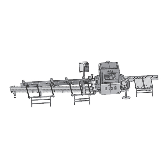
The Alpine ALS 4.0 takes linear cutting to
the next level. The ALS 4.0 is designed for
production efficiency, only requiring one
sawyer for operation. The result is a reduction
in labor, a boost in production and an increase
to your bottom line.
This is not only an operation manual, but a
tool that can be utilized to gain the maximum
potential from your ALS 4.0 linear saw. Each
plant runs differently and the ALS 4.0 stands up
to the challenge—providing ultimate flexibility
in setup and operation.
ALS 4.0 XE
Product Manual
EN
Advertisement
Table of Contents
Troubleshooting

Related Manuals for ITW Alpine ALS 4.0 XE

Summary of Contents for ITW Alpine ALS 4.0 XE
- Page 1 The Latest The Alpine ALS 4.0 takes linear cutting to the next level. The ALS 4.0 is designed for production efficiency, only requiring one Evolution of the sawyer for operation. The result is a reduction in labor, a boost in production and an increase Industry’s Leading to your bottom line.
- Page 2 ALS 4.0 XE P R O D U C T M A N UA L Read the following safety information before using this equipment: In this installation guide, the words WARNING, CAUTION and NOTE are used to emphasize important safety information as follows: WARNING CAUTION NOTE...
-
Page 3: Table Of Contents
ALS 4.0 XE P R O D U C T M A N UA L Contents 1. Introduction ........5 3.7.4 Nesting . - Page 4 ALS 4.0 XE P R O D U C T M A N UA L Contents (continued) 6. Troubleshooting ........65 Incorrect Homing/Cannot Home the Machine .
-
Page 5: Introduction
• Power Cable,LXM 52,16.4 ft 41039 (Used in L1 & L2) Copyright ©2021 by Alpine, a division of ITW Building Components Group Inc. All rights reserved. • Power Cable,LXM 52,19.68ft 41040 No part of this document may be reproduced, stored in a retrieval system,... -
Page 6: General Specifications
ALS 4.0 XE P R O D U C T M A N UA L General Specifications 1.2.1 Machine Capacity Lumber Size Range Width 2.38” (64mm) 14” (355mm) Thickness 1.38” (35mm) 1.77” (45mm) Length 6” (152mm) 24’ (without additional support) ... -
Page 7: Equipment Specifications
ALS 4.0 XE P R O D U C T M A N UA L 1.2.2 Equipment Specifications High Performance (H/HB) Saw Blade Diameter Custom 20.5” Spindle Motor (S-axis) Max RPM 2800 rpm ±1/16” Accuracy Infeed (L1-axis) Max Speed 160 in/sec Accuracy ±1/16”... -
Page 8: Service Requirements
ALS 4.0 XE P R O D U C T M A N UA L Axes of Motion 1.2.3 Service Requirements CAUTION Refer to Figure 2 (on page 9). The use of a qualified electrician is required to ensure the Spins the saw blade following service specifications are properly met. - Page 9 ALS 4.0 XE P R O D U C T M A N UA L Figure 1 Figure 2...
-
Page 10: Sensors
ALS 4.0 XE P R O D U C T M A N UA L Sensors Operator Console There are two sensor sets in the ALS 4.0. They are used Major functions of the machine are controlled from the to control the feeding and clamping of the lumber. keyboard, mouse, and flat panel or touchscreen monitor (optional) in the Operator’s Console. -
Page 11: Usb Device
ALS 4.0 XE P R O D U C T M A N UA L AUTOMODE – Automatic saw operation mode. It is also recommended that the saw computer have internet access. This will allow for remote access by Data is read from the saw computer, USB drive, or Alpine for troubleshooting and diagnostic evaluation. -
Page 12: Auto Screen
ALS 4.0 XE P R O D U C T M A N UA L Auto Screen CHANGE JOB LOCATION – Allows user input to specify the computer path to the location where the jobs are stored. This path can be any location that is accessible from the saw computer. -
Page 13: Current Stock Length Menu
ALS 4.0 XE P R O D U C T M A N UA L 3.2.3 Utility Tools Click on the utility tool icon and the following menu screen will appear: 1. MARK PIECE CUT – Will mark the piece you have selected as completely cut. -
Page 14: Create A Pick List
ALS 4.0 XE P R O D U C T M A N UA L 3.2.4 Create a Pick List When you touch the button and have the Create Pick List option checked in General Options the program will create a pick list for the current job. You can create the Pick List at the saw in regular operating mode or in the office in Office Mode. -
Page 15: Automatic Screen Operations
ALS 4.0 XE P R O D U C T M A N UA L Automatic Screen Operations OK – This button is used only during Office Mode operation of the program. It switches the program to the Cut Screen simulating detection of a board. 3.3.1 Load Lumber Screen When running a single stock length, the OK button... -
Page 16: Cut Status Screen
ALS 4.0 XE P R O D U C T M A N UA L 3.3.2 Cut Status Screen NEXT STOCK PIECE LAYOUT – Provides advance notice of the next piece of stock that will need to be loaded into the saw for cutting. This information is always to view what is coming next. -
Page 17: Change Stock Screen (Single Stock Option)
ALS 4.0 XE P R O D U C T M A N UA L 3.3.3 Change Stock Screen 3.3.4 Change Stock Screen (Single Stock Option) (Multi Stock Option) Figure 16 Figure 18 When Match Grade-Size is selected, the Multiple Stocks screen will appear as shown in Figure 18. -
Page 18: Semi-Automatic Operation
ALS 4.0 XE P R O D U C T M A N UA L 3.4.1 Board Select The SIZE and GRADE buttons will bring up screens when clicked. Here, the appropriate entries can be chosen. Click or touch SEMIMODE on the main menu to Within this dialogue box the following can be changed: advance to the Board Select Menu. -
Page 19: Semi-Auto Save
ALS 4.0 XE P R O D U C T M A N UA L QTY TO CUT – Click or touch the box and enter the 3.4.3 Bevel quantity required for the setup. BEVELS brings up the following screen. SAVE –... -
Page 20: Manual Control
ALS 4.0 XE P R O D U C T M A N UA L SAFETY SENSORS – This area shows the status of NOTE all the Operator Safety sensors . When settings have been completed the bevel section, check the PROXIMITY BOARD SENSORS –... - Page 21 ALS 4.0 XE P R O D U C T M A N UA L 10. CAL Functions – Each of these buttons brings 12. RESET – Resets Axes Drives and System faults. up a message like this: 13. ERROR LOG – Open error log. 14.
-
Page 22: System Options Menu
ALS 4.0 XE P R O D U C T M A N UA L System Options Menu Strip Layout Tag – The cut data file (*.TRS) contains two truss ID’s. One is automatically assigned by the VIEW Layout Program and the other is assigned by engineers in your office. -
Page 23: Pick List Options (3)
ALS 4.0 XE P R O D U C T M A N UA L There are seven pieces in the list shown here. You can enter a maximum of 12. These particular pieces are end blocks (EB), ribbon blocks (RB), and diagonal webs (Diag) for 14 and 16-inch-deep Modified Warren floor trusses. - Page 24 ALS 4.0 XE P R O D U C T M A N UA L Dead Reckoning Inventory System – This is a simple, For the example Standard Piece List presented earlier common sense system for making sure that the you would need six bins (similar to the diagram above) Standard Piece function produces enough, but not too to store the Standard Pieces when they are cut by...
-
Page 25: Pick List Sort Options (7)
ALS 4.0 XE P R O D U C T M A N UA L 3.6.7 Pick List Sort Options (7) 3.6.8.1 Ink Jet Setup Click or touching SETUP in the Ink Jet Setup section (Figure 34) will bring up the following screen: Figure 35 The Print Data information on the right side of this screen allows customization the information that is... -
Page 26: Bevel Options (9)
ALS 4.0 XE P R O D U C T M A N UA L CAT Length Adj – This adjustment is for the unique circumstance of single bevels on both ends that are parallel to each other that occurs when cutting CATS (filler members at the pitch break between step down hip trusses). -
Page 27: Advanced Options (10)
ALS 4.0 XE P R O D U C T M A N UA L Longest Pc 1st – Causes the Optimizer to look through the job for the longest uncut piece that will fit on the stock each time it places a piece for cutting. This is helpful when your files are not sorted long to short and you want the longer pieces to be cut first for stacking purposes. - Page 28 ALS 4.0 XE P R O D U C T M A N UA L Single-Single Single-Double Double-Double Single Bevels Bottom Chord Figure 38 4. NESTING OPTIONS NOTE The default settings for Nesting is currently disabled in the ALS 4.0 Software Settings. 5.
-
Page 29: Optimizer
ALS 4.0 XE P R O D U C T M A N UA L Optimizer 3.7.2 How it Works For a given length of stock, the Optimizer looks through 3.7.1 Introduction a cutting file for a combination of pieces that can be cut from that stock with minimum waste. -
Page 30: Optimizer Options
ALS 4.0 XE P R O D U C T M A N UA L For the most effective optimization and material Using the Optimizer, cutting potential was maximized and waste was minimized. handling ease, it is recommended to follow the steps below: Below is a comparison of an ALS 4.0 and a component saw. -
Page 31: Nesting
ALS 4.0 XE P R O D U C T M A N UA L • Combine all Grades – When this option is 3.7.4 Nesting checked, the computer will choose from all Found in Figure 28 of Section 3.5.3, these options turn pieces of the same size without regard to a grade on the nesting function for the type of joint interfaces requirement. -
Page 32: Pick List Options
ALS 4.0 XE P R O D U C T M A N UA L 3.7.6 Pick List Options 3.7.8 Optimizing Example The following options can be selected on the screen There are many ways to configure the software options shown in Figure 28, section 3.5.3: for Optimizing. -
Page 33: Additional Options
ALS 4.0 XE P R O D U C T M A N UA L When the job used in this example is cut, the 20 ft. 2x4 SP SS boards will be cut first as they are first on the pick list. -
Page 34: Names/Paths
ALS 4.0 XE P R O D U C T M A N UA L • Waste Shift Min – The start of an exclusion zone 3.9.2 How it works designed to eliminate final moves that place the Once pieces that are used frequently across cutting end of the waste at the edge of the roller nearest operations have been identified, they can be set as the blade... -
Page 35: Creating A Pick List
ALS 4.0 XE P R O D U C T M A N UA L The selected piece will be automatically added to the Standard Piece List. For each individual piece the quantity can be modified. NOTE The piece description from the job is saved to the Standard Piece List and cannot be changed. -
Page 36: Auto Infeed System
ALS 4.0 XE P R O D U C T M A N UA L This screen allows user to view current Pick List, Current The following describes the function of each button: Run List (the actual list of stock fills which are sent to LIVEDECK FWD –... -
Page 37: Xml Files
ALS 4.0 XE P R O D U C T M A N UA L 3.12 XML Files AXIS PARAMETER A1-B1-T1 – This tab has speed, accel, decel, software limits and other mechanical AlpineLE.xml is a file that contains parameters that settings for A1,B1 AND T1 Axes. -
Page 38: Calibration Procedure
ALS 4.0 XE P R O D U C T M A N UA L 4. Calibration Procedure NOTE The Manual Control Screen is referenced throughout this section. Check Gap Here Please see Figure 26 when this screen in referenced. Turn Off Power Step 1 –... -
Page 39: Calibrate Bevel Axis (B1)
ALS 4.0 XE P R O D U C T M A N UA L Calibrate Bevel Axis (B1) Step 1 – Place a magnetic digital angle gauge on the Z1 linear rails, as shown in Figure 63. Figure 65 Step 7 –... -
Page 40: Calibrate The Cut Angle (A1)
ALS 4.0 XE P R O D U C T M A N UA L Step 12 – Read the digital angle gauge. If it shows 180° then the axis is calibrated. If not, using the B1 axis jog Step 4 – Move A1 axis to 90° buttons on the Manual Control Screen, jog the B1 axis using the Move A1 button on until the gauge reads 180°. -
Page 41: Calibrate Center Of Rotation
ALS 4.0 XE P R O D U C T M A N UA L Step 10 – Release L1 Clamp using “L1 Clamp Up” button. Step 15 – The A1 axis is now ready to calibrate. Touch the CAL A1 button in the Manual Control Screen. Step 11 –... - Page 42 ALS 4.0 XE P R O D U C T M A N UA L Step 7 – Move A1 to 90° using Step 13 – Move Z1 back to “0.0” the “Move A1” button on the using the “Move Z1” button on Manual Control Screen.
-
Page 43: Calibrate Centerline (T1)
ALS 4.0 XE P R O D U C T M A N UA L Calibrate Centerline (T1) Step 18 – Open the door to the saw cabinet, shut down the computer, and then disconnect electricity and air Step 1 – Place a 2x4 board (dimensional lumber) across supply. - Page 44 ALS 4.0 XE P R O D U C T M A N UA L Step 15 – Release the L1 & L2 Clamps using the “L1 Clamp Up” and “L2 Clamp Up” buttons on the Manual Step 9 – Jog Z1 down using Control Screen.
-
Page 45: L1/L2 Belt Tension Adjustment
ALS 4.0 XE P R O D U C T M A N UA L Step 22 – The Figure below shows the hard stop for Lock nuts Drive belt the T-axis. If the centerline of the cut is less than 1.75”, extend the bolt. - Page 46 ALS 4.0 XE P R O D U C T M A N UA L Step 4 – To calibrate L1/L2, select “Controller” from the task bar at the bottom of the screen (Figure 112). Figure 112 The screen in Figure 113 will appear: Figure 115 Step 7 –...
-
Page 47: Check Alignment Of The T/Z Slide & Belt Feeders
ALS 4.0 XE P R O D U C T M A N UA L 4.10 Check Alignment of the Step 6 – Move T1 to “-2” using the “Move T1” button on the Manual Control Screen T/Z Slide & Belt Feeders Step 1 –... - Page 48 ALS 4.0 XE P R O D U C T M A N UA L Step 9 – Manually Jog T1 forward until a groove has Step 12 – Stop the blade using the “Saw Motor Off” been cut across the full width of the lumber using the button on the Manual Control Screen.
-
Page 49: Maintenance
ALS 4.0 XE P R O D U C T M A N UA L 5. Maintenance Parts Identification 5.1.1 Inkjet Printer Printer Ink Cables – APN 26344 Printer Sensor Cable – APN 20662 Infeed Roller - APN 38081 Printer Head – APN 33795 Photo Sensor (Printer) –... - Page 50 ALS 4.0 XE P R O D U C T M A N UA L L1 Assembly – APN 34325 L1 Belt – APN 29107 Drive Shaft – APN 31026 Figure 135 Shafts – APN 29988 Receiver – APN 23141 L1 motor –...
- Page 51 ALS 4.0 XE P R O D U C T M A N UA L L2 Shafts – APN 29988 L2 Receiver – APN 23141 L2 Motor – APN 41020 Figure 138 A1 Axis Belt – APN 28979 T1 Axis Motor – APN 41010 T1 Gearbox (not pictured) –...
-
Page 52: Automated Infeed
ALS 4.0 XE P R O D U C T M A N UA L B1 Axis Motor – APN 41009 (viewed from back of saw) Figure 141 5.1.3 Automated Infeed Chain – APN 70472 Infeed Sensor (not pictured) – APN 24664 Infeed Sensor Motor (not pictured) –... -
Page 53: Outfeed
ALS 4.0 XE P R O D U C T M A N UA L 5.1.4 Outfeed Belt Adjustment Screw – APN 27067 Parts Sorting Conveyor Tail Shaft – APN 34009 (Bearing – APN 21993) Figure 144 Parts Sorting Conveyor Tail Shaft – APN 34009 (Bearing - APN 21993) Waste Conveyor Tail shaft –... - Page 54 ALS 4.0 XE P R O D U C T M A N UA L Tail Shaft (Roller) – APN 32759 Figure 147 Sorting Belt – APN 27032 Waste Belt – APN 30803 Figure 148 Vortec Cooler Filter Regulator – APN 37157 Adjustment Bearing –...
-
Page 55: Main Saw Electrical Cabinet
ALS 4.0 XE P R O D U C T M A N UA L 5.1.5 Main Saw Electrical Cabinet Figure 150 TAG NO. DESCRIPTION #APN TAG NO. DESCRIPTION #APN DR 208 41075 CB 100 42501 Servo Drive 18 Amp Peak, L1P Axis Miniature Circuit Breaker, 3 Pole, 240VAC 6 Amps DR 217 41068... -
Page 56: Printer Electrical Cabinet
ALS 4.0 XE P R O D U C T M A N UA L 5.1.6 Printer Electrical Cabinet Figure 151 TAG NO. DESCRIPTION CR-735 Relay, 4PDT, 6 Amp, Rectangular, Plug-In, 14 Pin, 24 Vdc Non-Lighted Coil CR-720 Relay, 4PDT, 6 Amp, Rectangular, Plug-In, 14 Pin, 24 Vdc Non-Lighted Coil PLC-BASE PLC, Fieldbus Bus Interface CB-704... -
Page 57: Cleaning
ALS 4.0 XE P R O D U C T M A N UA L Cleaning Machine Lubrication Clean sawdust out of the machine at the end of each See the included maintenance log for lubrication shift of operation. intervals (Appendix A). This section includes the locations where grease will be added per the The L1 &... - Page 58 ALS 4.0 XE P R O D U C T M A N UA L L1 & L2 Clamps: On the back of the saw cabinet, Outfeed Queue Conveyor: There are 3 shafts under there are 2 sets of grease blocks, one for the L1 Clamp the outfeed queue.
-
Page 59: Automated Infeed
ALS 4.0 XE P R O D U C T M A N UA L Automated Infeed EXLAR® Actuator Maintenance CAUTION There are 4 grease fittings on the bearing block for the printer encoder wheel. The fittings can be accessed from Alpine recommends wearing disposable Nitrile gloves when the rear of the machine (4 total). - Page 60 ALS 4.0 XE P R O D U C T M A N UA L Step 3 – Enable the Axes by clicking or touching the NOTE button shown in Figure 164. The button that will then change to read “Enable Axes” as shown NOTE in Figure 167.
- Page 61 ALS 4.0 XE P R O D U C T M A N UA L Step 10 – Install belt, tension using Force on Idler as shown in Figure 172. Figure 169 Figure 172 CAUTION The idler pulley plate slot allows moving the idler pulley so the belt can be placed, followed by placing a force directly over the idler pulley to obtain the proper tension to tighten the belt to 23.4 lb.
-
Page 62: Removing The Z1 Actuator
ALS 4.0 XE P R O D U C T M A N UA L 5.5.2. Removing the Z1 Actuator Step 1 – Before removing the Z1 actuator, make sure the head is all the way down against the bottom hard stops. -
Page 63: Waste Conveyor Belt Tensioning
ALS 4.0 XE P R O D U C T M A N UA L Step 6 – Install the rod that connects the lacing (Figure WARNING 167) NEVER PUT ANY PART OF YOUR BODY NEAR THE MOVING BELT. Step 2 – Run conveyor to determine which way the belt is tracking. -
Page 64: Small Parts Conveyor
ALS 4.0 XE P R O D U C T M A N UA L 5.7.3 Small Parts Conveyor NOTE The belt used on the small parts conveyor features a self-tracking belt and does not track off of guide rollers. This offers a simplified process for belt replacement and tracking as detailed in the following steps. -
Page 65: Troubleshooting
ALS 4.0 XE P R O D U C T M A N UA L 6. Troubleshooting C O N D I T I O N C A U S E C H E C K C O R R E C T I O N Incorrect Homing/ No power The green LED which indicates... -
Page 66: Conveyor Will Not Start
ALS 4.0 XE P R O D U C T M A N UA L C O N D I T I O N C A U S E C H E C K C O R R E C T I O N Conveyor will not Start Machine is in E-Stop condition Check all E-Stop locations to... -
Page 67: Prints Same Information
ALS 4.0 XE P R O D U C T M A N UA L C O N D I T I O N C A U S E C H E C K C O R R E C T I O N Prints Same Print controller program closed Use the mouse to display the task... -
Page 68: Automated Infeed Bad Lumber Load
ALS 4.0 XE P R O D U C T M A N UA L C O N D I T I O N C A U S E C H E C K C O R R E C T I O N Automated Infeed Bad Warped or crooked lumber Visually inspect lumber before... -
Page 69: Pneumatic Cylinder Does Not Actuate Or Actuates Slowly
ALS 4.0 XE P R O D U C T M A N UA L C O N D I T I O N C A U S E C H E C K C O R R E C T I O N 6.12 Pneumatic Cylinder Low Air pressure (Air pressure Locate the regulator on outfeed of... -
Page 70: Bevel Troubleshooting
ALS 4.0 XE P R O D U C T M A N UA L C O N D I T I O N C A U S E C H E C K C O R R E C T I O N 6.15 Bevel Troubleshooting Encroaching adjacent pieces Check the Bevel Spacing setting... -
Page 71: E-Stop Troubleshooting
ALS 4.0 XE P R O D U C T M A N UA L C O N D I T I O N C A U S E C H E C K C O R R E C T I O N 6.16 E-Stop Troubleshooting Cannot recover from E-Stop Check all E-Stop buttons on the... -
Page 72: Error Log Diagnostics
ALS 4.0 XE P R O D U C T M A N UA L Error Log Diagnostics System Diagnostics and Troubleshooting This section will show how to diagnose, and trouble shoot when there is a fault in the machine operation. Touching icon 8 from the main screen will open the Manual Screen, from this screen the operator can view the status of all the machine... -
Page 73: Appendix A - Maintenance Intervals
ALS 4.0 XE P R O D U C T M A N UA L Appendix A – Maintenance Intervals ALS 4.0 Machine Inspection Guide and Maintenance Log Date _______/_______/_______ EVERY SHIFT / 8 HOURS Thur Clean saw dust off the machine with a vacuum cleaner (compressed air fills the environment with saw dust and debris and may cause a safety hazard). -
Page 74: Appendix B - Pneumatic System Schematic
ALS 4.0 XE P R O D U C T M A N UA L Appendix B – Pneumatic System Schematic... -
Page 75: Appendix B - Pneumatic System Schematic
ALS 4.0 XE P R O D U C T M A N UA L Appendix B – Pneumatic System Schematic – L1/L2 Blow-off... -
Page 76: Appendix C - Unit Conversion Tables
ALS 4.0 XE P R O D U C T M A N UA L Appendix C – Unit Conversion Tables fraction decimal fraction decimal fraction decimal fraction decimal 1/64 0.0156 17/64 0.2656 33/64 0.5156 49/64 0.7656 1/32 0.0313 9/32 0.2813 17/32 0.5313... - Page 77 ALS 4.0 XE P R O D U C T M A N UA L inches inches inches inches 0.0039 0.9055 2.1260 3.3464 0.0079 0.9449 2.1653 3.3858 0.0118 0.9842 2.2047 3.4252 0.0157 1.0236 2.2441 3.4646 0.0197 1.0630 2.2835 3.5039 0.0236 1.1024 2.3228 3.5433...
-
Page 78: Appendix D - Terms Glossary
ALS 4.0 XE P R O D U C T M A N UA L Appendix D – Terms Glossary Bevel – an edge of a structure that is not perpendicular Joint – The point at which two or more peices of wood to the face of the piece. -
Page 79: Appendix E - Warranty
Appendix E – Warranty Warranty ALS 4.0 Alpine, a division of ITW Building Components Group Inc. If warranty service is required and booked by the buyer (hereinafter referred to as “Alpine”) warrants the ALS 4.0 with Alpine, the buyer must provide notice of cancellation to be free from defects in materials and workmanship for of the service order within 24 hours of booking. - Page 80 155 Harlem Avenue North Building – 4th Floor Glenview, Illinois 60025 800-521-9790 alpineitw.com ©2023 Alpine, a division of ITW Building Components Group Inc. Form M1026-R2 05/23...
Need help?
Do you have a question about the Alpine ALS 4.0 XE and is the answer not in the manual?
Questions and answers
[Type ISH HP ser.No 28936] the pressure gauge reads 1 psi or less, appears to have loss of pressure, and the knob doesn't move the needle up or down. leaving the ink difficult to read. However when i flush ink with the TightVNC viewer it sprays well.
The cause of a low-pressure reading on the ITW Alpine ALS 4.0 XE pressure gauge could be low or no air pressure reaching the system. This can happen due to air leaks, a faulty regulator, or issues in the air supply. If the knob does not adjust the needle, it may indicate a malfunctioning regulator, a blockage in the air line, or an issue with the air compressor. Checking for air leaks and ensuring the regulator functions properly can help resolve the issue.
This answer is automatically generated
how do i change the location of where the ink gets sprayed. Currently spray on the end of the board, how do i get it to print in the middle?