Table of Contents
Advertisement
Quick Links
3714 Kinnear Place
Saskatoon, SK
GROUND-FAULT GROUND-CHECK MONITOR
Document Number: PM-1305-EN
Printed in Canada.
Canada
S7P 0A6
Ph: (306) 373-5505
SE-107 MANUAL
REVISION 5-C-050715
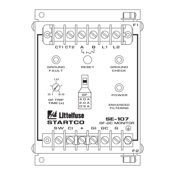
C T 1 C T 2 A
G R O U N D
R E S E T
F A U L T
1 . 0
G F
0 . 1
2 . 0
4 . 0 A
G F T R I P
2 . 0 A
T I M E ( s )
0 . 5 A
S W
C I
Copyright
2015 by Littelfuse Startco
All rights reserved.
Fx: (306) 374-2245 www.littelfuse.com/relayscontrols
F 1
B
L 1
L 2
G R O U N D
C H E C K
P O W E R
E N H A N C E D
F I LT E R I N G
G I
G C
G
F 2
Advertisement
Table of Contents

Subscribe to Our Youtube Channel
Related Manuals for Littelfuse Startco SE-107


Summary of Contents for Littelfuse Startco SE-107
- Page 1 T I M E ( s ) E N H A N C E D 0 . 5 A F I LT E R I N G Copyright 2015 by Littelfuse Startco All rights reserved. Document Number: PM-1305-EN Printed in Canada.
- Page 2 Page i SE-107 Ground-Fault Ground-Check Monitor Rev. 5-C-050715 This page intentionally left blank.
-
Page 3: Table Of Contents
2.3 Indication and Reset ..........1 Specifications are subject to change without notice. 2.4 Fusing ..............1 Littelfuse Startco is not liable for contingent or Installation ............1 3.1 SE-107 ..............1 consequential damages, or for expenses sustained as a 3.2 Ground-Fault CT ........... - Page 4 Page iii SE-107 Ground-Fault Ground-Check Monitor Rev. 5-C-050715 This page intentionally left blank.
-
Page 5: Gf Trip Time
The output contact is protected by fuse F1 (4.0 A, time GC-1. delay). The ground-check circuit is protected by fuse F2 (0.5 A, time delay). : The SE-107 is not a lock-out device. Follow AUTION lock-out procedures for maintenance. 3. I NSTALLATION 2. - Page 6 Page 2 SE-107 Ground-Fault Ground-Check Monitor Rev. 5-C-050715 CT200 LOAD GROUND START STOP 120 VAC GROUND CHECK NOTE 1 HOLD-IN USE LOW- NOTE 1 CONTACT LEVEL CONTACTS ALTERNATE TERMINATION CIRCUIT GROUND-CHECK FOR REMOTE CONTACTOR CONTROL C T 1 C T 2 A...
- Page 7 CT, return them through the CT before connecting them to ground. Connect the secondary of the ground-fault CT to SE-107 terminals CT1 and CT2. The CT connection to the SE-107 is not polarity sensitive. Ground one side of the CT secondary.
-
Page 8: Terminal Designations
Fig. 13 shows test circuits using the SE-400 Termination outlines and mounting details are shown in Ground-Fault-Relay Test Unit and the SE-100T Ground- Figs. 4, 5, and 6. Use only a Littelfuse Startco termination Fault-Relay Tester. The SE-400 has a programmable device;... - Page 9 Page 5 SE-107 Ground-Fault Ground-Check Monitor Rev. 5-C-050715 44.5 MAX (1.75) NOTES: 1. DIMENSIONS IN MILLIMETRES (INCHES). 2. MOUNTING SCREWS: M4 OR 8-32. BLACK WHITE SIDE FRONT (0.37) TAP M4 OR 8-32 BOTTOM MOUNTING DETAIL DIMENSIONS PART NUMBER 55.9 (2.20) 120.7 (4.75)
- Page 10 Page 6 SE-107 Ground-Fault Ground-Check Monitor Rev. 5-C-050715 41.5 40.0 (1.63) (1.57) 40.0 22.2 10.5 19.0 (1.57) (0.87) (0.41) (0.75) S E - T A 6 T E R M I N A T I O N A S S E M B L Y...
- Page 11 Page 7 SE-107 Ground-Fault Ground-Check Monitor Rev. 5-C-050715 30.0 (1.18) RESET GROUND CHECK GROUND FAULT LEGEND PLATE NOTE 2 22.2 (0.87) DIA 17.3 36.6 29.9 (0.68) (1.44) (1.17) LEGEND PLATES NOTES: LED PILOT LIGHTS 1. DIMENSIONS IN MILLIMETRES (INCHES). 2. ----- INDICATES CLEARANCE 30.0 MINIMUM...
- Page 12 1. DIMENSIONS IN MILLIMETRES (INCHES). 2. NEMA 1. FIGURE 9. RK-105I Remote Indication Assembly. CI/GI GI/RI SIDE VIEW RK-13 SHOWN MOUNTED ON SE-105/SE-107/SE-325 60.2 (2.37) INSTALLATION INSTRUCTIONS: 1. REMOVE FOUR LEFTMOST LOWER TERMINAL BLOCK SCREWS. 2. PLACE RK-13 ON TERMINAL BLOCK AND REPLACE SCREWS.
- Page 13 Page 9 SE-107 Ground-Fault Ground-Check Monitor Rev. 5-C-050715 9.5 DIA. (0.38 DIA.) 8-32 TAP 260.4 (10.25) 34.9 34.9 190.5 (7.50) (1.38) (1.38) 152.4 (6.00) 235.0 (9.25) NOTES: DIMENSIONS IN MILLIMETRES (INCHES). FIGURE 11. PPI-600V Parallel-Path Isolator.
- Page 14 Page 10 SE-107 Ground-Fault Ground-Check Monitor Rev. 5-C-050715 GROUND CHECK MONITOR SE-105, SE-107, SE-134C, OR SE-135 GROUND CABLE CHECK GROUND OUTGOING GROUND CHECK OUTGOING GROUND INCOMING GROUND CHASSIS GROUND BUS PPI-600V NOTES: 1. THE PARALLEL-PATH ISOLATOR IS NOT POLARIZED. EITHER FLANGE CAN BE CONNECTED TO CHASSIS.
-
Page 15: Output Relay
Page 11 SE-107 Ground-Fault Ground-Check Monitor Rev. 5-C-050715 Trip-Time Accuracy ... +10, -30% 5. T ECHNICAL PECIFICATIONS GC-Loop ....40 ± 10 5.1 SE-107 Trip Resistance Operating Mode....Non-Latching, Supply: Latching with Option L ac ..........10 VA, 120 or 240 Vac... -
Page 16: Current Sensors
Page 12 SE-107 Ground-Fault Ground-Check Monitor Rev. 5-C-050715 Certification ......CSA, Canada and USA SE-TA6ASF-WL: Characteristic ...... 6-V Zener, Temperature LR 53428 Compensated Circuit Type ......High-Current Shunt UL Listed Regulator Reverse Voltage ....5.6 ±0.03 Vdc @ 100 mA Forward Voltage .... -
Page 17: Ground-Fault Ct
E 240-Vac Supply D 120-Vac/dc Supply repair, replace, or refund the original purchase price of an Each SE-107 is supplied with a 1N5339B termination device. SE-107 that is determined by Littelfuse Startco to be List options required in order shown above. -
Page 18: Ground-Fault Performance Test
0.5 to 9.9 A for a duration of 0.1 to 9.9 seconds. Set the test current to 0.6, 2.3, or 4.6 A for SE-107 units set at 0.5, 2.0, or 4.0 A respectively. Fig. 13b shows a test circuit using an SE-100T Ground-Fault Relay Tester. -
Page 19: Se-107
Page 15 SE-107 Ground-Fault Ground-Check Monitor Rev. 5-C-050715 APPENDIX A SE-107 REVISION HISTORY MANUAL MANUAL PRODUCT REVISION RELEASE DATE REVISION (REVISION NUMBER ON PRODUCT LABEL) May 7, 2015 5-C-050715 April 29, 2015 5-B-042915 September 11, 2014 5-A-091114 ANUAL EVISION ISTORY... - Page 20 Page 16 SE-107 Ground-Fault Ground-Check Monitor Rev. 5-C-050715 This page intentionally left blank.
Need help?
Do you have a question about the SE-107 and is the answer not in the manual?
Questions and answers