Table of Contents
Advertisement
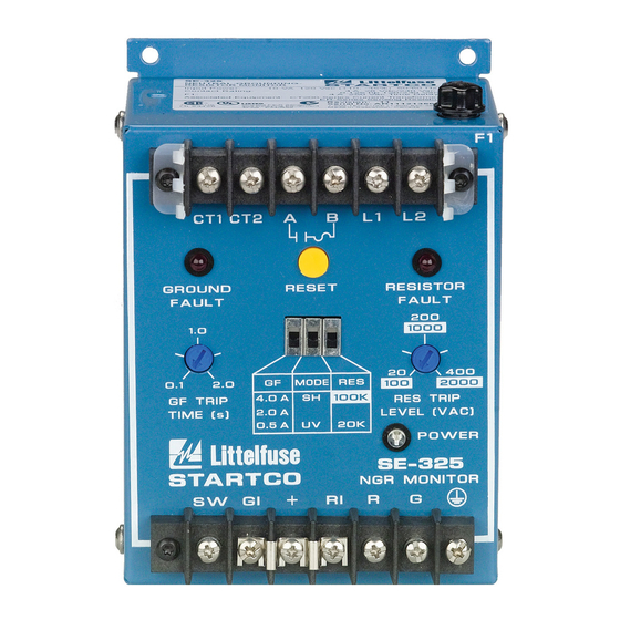
NEUTRAL-GROUNDING-RESISTOR MONITOR
Publication: SE-325-M
Document: S95-C325-00000
Printed in Canada.
SE-325 MANUAL
MAY 6, 2008
REVISION 10
C T 1 C T 2 A
G R O U N D
R E S E T
F A U L T
1 . 0
G F
M O D E R E S
0 . 1
2 . 0
G F T R I P
4 . 0 A
T I M E ( s )
2 . 0 A
0 . 5 A
S T A R T C O
E N G I N E E R I N G L T D .
S W
G I
Copyright © 2008 by Startco Engineering Ltd.
All rights reserved.
F 1
B
L 1
L 2
R E S I S TO R
F A U L T
2 0 0
2 0
4 0 0
S H
R E S T R I P
L E V E L ( V A C )
U V
2 0 K
P O W E R
S E - 3 2 5
N G R M O N I T O R
R I
R
G
Advertisement
Table of Contents

Related Manuals for Littelfuse Startco SE-325


Summary of Contents for Littelfuse Startco SE-325
- Page 1 SE-325 MANUAL NEUTRAL-GROUNDING-RESISTOR MONITOR MAY 6, 2008 REVISION 10 C T 1 C T 2 A G R O U N D R E S E T R E S I S TO R F A U L T F A U L T 2 0 0 1 .
- Page 2 This page intentionally left blank.
-
Page 3: Table Of Contents
IGURES IGURE Table of Contents ..............i Typical Application ............3 List of Figures................i SE-325 Outline and Mounting Details......4 List of Tables ................i Current Transformers............ 5 ER-600VC Sensing Resistor ........6 General ................. 1 ER-5KV Sensing Resistor ..........7 1.1 Modern Resistance-Grounded Systems ....... -
Page 4: Se-325 Neutral-Grounding-Resistor Monitor Rev
Startco Engineering Ltd. Page ii SE-325 Neutral-Grounding-Resistor Monitor Rev. 0 This page intentionally left blank. Pub. SE-325-M, May 6, 2008. -
Page 5: General
1.2 SE-325 NGR M ONITORING exists in low-resistance- or solidly grounded systems and The SE-325 is a neutral-grounding-resistor monitor for a ground-fault can result in substantial point-of-fault resistance-grounded systems up to 25 kVac. It measures damage. -
Page 6: Mode
Red LED's indicate ground-fault and resistor- occurs. The shunt-trip mode is not fail-safe because shunt- fault trips. When a trip occurs, the SE-325 remains latched trip devices do not operate if supply voltage fails. until the reset switch is pressed or supply voltage is cycled. -
Page 7: Installation
NSTALLATION 3.1 SE-325 Face-plate LED's are driven in series with remote- SE-325 outline and mounting details are shown in indication LED's. When remote-indication LED’s are not Fig. 2. Typical connections are shown in Fig. 1. Connect used, terminals GI, +, and RI must be connected for the supply voltage to L1 and L2. -
Page 8: Se-325 Outline And Mounting Details
4 . 8 ( 0 . 1 9 ) D I A TERMINAL-BLOCK SCREWS: 6-32 x 0.25. MOUNTING SCREWS: M4 OR 8-32. SHOWN WITH TERMINAL-BLOCK COVER REMOVED. MINIMUM CLEARANCE FOR FUSE REMOVAL. FIGURE 2. SE-325 Outline and Mounting Details. Pub. SE-325-M, May 6, 2008. -
Page 9: Ground-Fault Ct
Outline and mounting details for CT200 and CT200L Connect the secondary of the ground-fault CT to SE-325 current transformers are shown in Fig. 3. Ground-fault-CT terminals CT1 and CT2. The CT connection to the SE-325 connections and the typical ground-fault-CT location are is not polarity sensitive. -
Page 10: Sensing Resistor
THIS CONNECTION MAY BE REMOVED FOR DIELECTRIC STRENGTH TESTING. ENSURE THAT THE JUMPER IS INSTALLED AFTER TESTING. ON REVISION 1 UNITS, SCREW IS NOT PRESENT AND ENCLOSURE IS ELECTRICALLY CONNECTED TO TERMINAL G. FIGURE 4. ER-600VC Sensing Resistor. Pub. SE-325-M, May 6, 2008. -
Page 11: Er-5Kv Sensing Resistor
STRENGTH TESTING. ENSURE THAT THE JUMPER IS INSTALLED (18.00) AFTER TESTING. ON REV 0 & 1 UNITS SCREW IS NOT MOUNTING DETAIL PRESENT AND BASE IS ELECTRICALLY CONNECTED TO TERMINAL G. FIGURE 5. ER-5KV Sensing Resistor. Pub. SE-325-M, May 6, 2008. -
Page 12: Er-15Kv Sensing Resistor
2. TERMINAL-BLOCK SCREWS: NOTE 3 6-32 x 0.25. MINIMUM CLEARANCE FROM BASE 3. MOUNTING SCREWS: 305.0 (12.00) M6 OR 0.25-20. 4. USE LIQUID-TIGHT GLAND FOR TERMINAL-BLOCK-ENCLOSURE CABLE ENTRY. MOUNTING DETAIL FIGURE 6. ER-15KV Sensing Resistor. Pub. SE-325-M, May 6, 2008. -
Page 13: Er-25Kv Sensing Resistor
6-32 x 0.25. 3. MOUNTING SCREWS: MINIMUM CLEARANCE FROM BASE M6 OR 0.25-20. 508.0 (20.00) 4. USE LIQUID-TIGHT GLAND FOR TERMINAL-BLOCK- ENCLOSURE CABLE ENTRY. MINIMUM DISTANCE TO ADJACENT OBJECTS MOUNTING DETAIL FIGURE 7. ER-25KV Sensing Resistor. Pub. SE-325-M, May 6, 2008. -
Page 14: Rk-302 Remote Indication And Reset
D I A 2 2 . 2 5 ( 0 . 8 7 5 ) SIDE VIEW FRONT VIEW MOUNTING DETAIL NOTES: 1. DIMENSIONS IN MILLIMETRES (INCHES). 2. NEMA 1. FIGURE 9. RK-325 Remote Indication-and-Reset Assembly. Pub. SE-325-M, May 6, 2008. -
Page 15: Rk-325I Remote Indication Assembly
1. DIMENSIONS IN MILLIMETRES (INCHES). 2. NEMA 1. FIGURE 10. RK-325I Remote Indication Assembly. CI/GI GI/RI SIDE VIEW RK-13 SHOWN MOUNTED ON SE-105/SE-107/SE-325 60.2 (2.37) INSTALLATION INSTRUCTIONS: 1. REMOVE FOUR LEFTMOST LOWER TERMINAL BLOCK SCREWS. 2. PLACE RK-13 ON TERMINAL BLOCK AND REPLACE SCREWS. -
Page 16: Isolated-Ground Connection
Option H required, use an RK-13 Relay Interface Module. Trip Time......0.1 to 2.0 s, RK-13 mounts on the SE-325 lower terminal block and it is 0.1 to 5.0 s with compatible with the RK-302, RK-325 and RK-325I. See Option T Figs. -
Page 17: Sensing Resistors
Contact Ratings ....100 mA, 120 Vac Australia Contact Configuration ..N.O. (Form A) Reset Input ......24 to 120 V (ac or dc), Isolated Commonwealth of Pennsylvania SE-325..BOTE 1767-99 PWB Conformal Coating..MIL-1-46058 qualified, SE-325P..BOTE 1797-00 UL QMJU2 recognized Pub. SE-325-M, May 6, 2008. -
Page 18: Ordering Information
N Non-latching Operation D 120-Vac/dc Supply SE-325 that is determined by Startco to be defective if it T Extended G-F Trip Time is returned to the Startco factory, freight prepaid, within the warranty period. -
Page 19: Test Procedures
0.5 to 9.9 A for a duration of 0.1 to 9.9 seconds. Set the test current to 0.6, 2.3, or 4.6 A for SE-325 units set at 0.5, 2.0, or 4.0 A FIGURE 12. Ground-Fault-Test Circuits respectively. Fig. 12b shows a test circuit using a Startco SE-100T Ground-Fault-Relay Tester. -
Page 20: Resistor-Fault Tests
Test Equipment: 0 to 120 Vac voltage source and multimeter. Applying the test voltage to the R and G terminals will OTE: damage the SE-325 and the ER sensing resistor. The RES TRIP LEVEL is the trip voltage at terminal N, not terminal R. Procedure: •...