Table of Contents
Advertisement
Quick Links
WHITE-RODGERS
Operator: Save these instructions for future use!
FAILURE TO READ AND FOLLOW ALL INSTRUCTIONS CAREFULLY
BEFORE INSTALLING OR OPERATING THIS CONTROL COULD CAUSE
PERSONAL INJURY AND/OR PROPERTY DAMAGE.
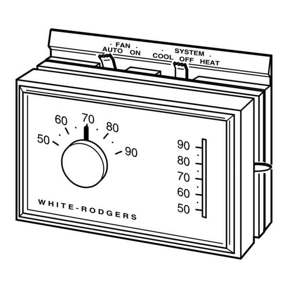
These low voltage thermostats are designed to provide
convenient control of the heating/cooling system. To
provide greater room comfort, the sensitive spiral bimetal
is combined with an adjustable heating anticipator and a
fixed cooling anticipator to provide maximum comfort.
If in doubt about whether your wiring is millivolt, line, or
low voltage, have it inspected by a qualified heating and
air conditioning contractor, electrician, or someone famil-
iar with basic electricity and wiring.
Do not exceed the specification ratings.
All wiring must conform to local and national electrical
codes and ordinances.
CONTENTS
Description ............................................................ 1
Precautions ........................................................... 1
Specifications ........................................................ 2
Installation ............................................................. 2
Electric Heat Furnaces (Single Transformer
Systems Only)
Operation & Maintenance ..................................... 5
ST. LOUIS, MISSOURI 63123-5398
1D56 and 1F56
Low Voltage Heating/Cooling Thermostat
INSTALLATION INSTRUCTIONS
This control is a precision instrument, and should be
handled carefully. Rough handling or distorting compo-
nents could cause the control to malfunction.
To prevent electrical shock and/or equipment
damage, disconnect electric power to system at
main fuse or circuit breaker box until installation
is complete.
Do not short out terminals on gas valve or pri-
mary control to test. Short or incorrect wiring will
burn out heat anticipator and could cause per-
sonal injury and/or property damage.
Do not use on circuits exceeding 30 volts. Higher
voltage will damage control and could cause
shock or fire hazard.
Printed in U.S.A.
DESCRIPTION
PRECAUTIONS
CAUTION
!
WARNING
!
PART NO. 37-4348E
Replaces 37-4348D
9716
Advertisement
Table of Contents

Related Manuals for White Rodgers 1D56


Summary of Contents for White Rodgers 1D56
-
Page 1: Table Of Contents
1D56 and 1F56 WHITE-RODGERS Low Voltage Heating/Cooling Thermostat INSTALLATION INSTRUCTIONS Operator: Save these instructions for future use! FAILURE TO READ AND FOLLOW ALL INSTRUCTIONS CAREFULLY BEFORE INSTALLING OR OPERATING THIS CONTROL COULD CAUSE PERSONAL INJURY AND/OR PROPERTY DAMAGE. DESCRIPTION These low voltage thermostats are designed to provide convenient control of the heating/cooling system. -
Page 2: Specifications
SPECIFICATIONS ELECTRICAL DATA APPLICATIONS The 1D56 and 1F56 are designed for use with Switch Rating: 24 VAC (30 VAC max.) • Standard heating and cooling systems Heating - 0.15 to 1.2 Amps • Electric heating and cooling systems Cooling - 0 to 1.5 Amps •... -
Page 3: Attach Subbase To Wall
Heat Pump Applications ATTACH SUBBASE TO WALL This subbase WILL NOT provide multi-stage heating or CAUTION cooling operation. For single-stage heat pump applica- tions, install a short jumper wire across terminals W and To prevent electrical shock and/or equipment Y. If the old thermostat has a terminal that is continuously damage, disconnect electric power to system at energized, disconnect the wire from the old thermostat’s main fuse or circuit breaker box until installation... - Page 4 CAUTION NOTE Take care when securing and routing wires so These typical wiring diagrams show only the terminal they do not short to adjacent terminals or rear of identification and wiring hookup. Always refer to wiring thermostat. Personal injury and/or property dam- instructions, provided by equipment manufacturer, for age may occur.
-
Page 5: Operation & Maintenance
KEEP THIS G RC AREA CLEAR OF WIRES! Factory-installed red jumper wire THERMOSTAT WIRING Factory-installed Field-installed yellow jumper wire jumper wire Factory-Installed Jumper Field-Installed Jumper TRANSFORMER Compressor Relay Relay SYSTEM 24 VAC 120 VAC Neutral Terminal energized Terminal energized in cooling in heating Figure 6. -
Page 6: Adjusting Heat Anticipator
ADJUSTING HEAT ANTICIPATOR 6. Move temperature adjustment lever to correspond to actual room temperature. Then remove thermostat cover. CAUTION 7. Slip ⁄ ” calibration wrench onto hex nut. While hold- The adjustable heat anticipator WILL BURN OUT ing temperature adjustment lever stationary, turn if 25 VAC is applied directly to the thermostat by hex nut counterclockwise until mercury just barely shorting out the primary control during testing.
Need help?
Do you have a question about the 1D56 and is the answer not in the manual?
Questions and answers