
Related Manuals for GFA ELEKTROMAT SI 45.15 FU-40,00


Summary of Contents for GFA ELEKTROMAT SI 45.15 FU-40,00
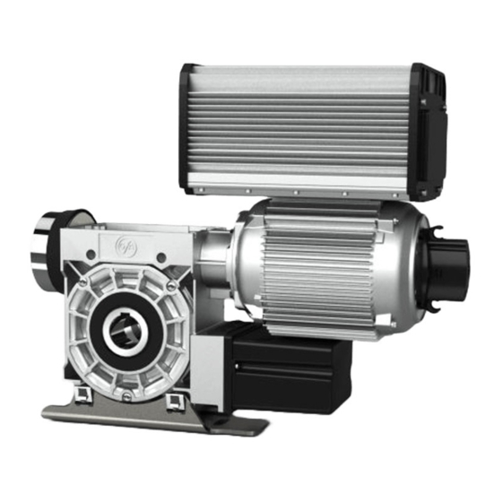
- Page 1 Installation Instructions ELEKTROMAT SI 45.15 FU-40,00 Model: 10004022 10011 -en- Status: 02.07.2023...
- Page 2 GfA ELEKTROMATEN GmbH & Co. KG Wiesenstraße 81 D-40549 Düsseldorf www.gfa-elektromaten.de info@gfa-elektromaten.de...
-
Page 3: Table Of Contents
Table of contents General safety information ....................4 Technical data ........................ 6 Integrated safety brake ....................7 Mechanical installation ....................8 Electrical installation ..................... 12 Limit switch adjustment ....................13 ... -
Page 4: General Safety Information
The safe operation of the product can only be ensured if it is used as specified. Follow the installation instructions. Observe all specifications, especially warnings, when installing the product in the overall system. GfA is not liable for damage resulting from non-observance of the installation instructions. The resulting overall system must be reassessed for its safety in accordance with applicable standards and directives (e.g. - Page 5 Warning - Failure to follow these installation instructions may result in severe injury or death. Please read these instructions before using the product. Keep these instructions handy. Include these instructions when passing on the product to third parties. Warning - Danger from improper use of the product! ...
-
Page 6: Technical Data
2 Technical data Designation Unit Output speed Output torque 450 (290) Output / hollow shaft 40,00 Series SG 85F Limit switch range (maximum revolutions of the output / hollow shaft) Supply voltage 1N~ 230 / 3~ 230 Operating current 7,30 Operating frequency 50/60 Power factor cos φ... -
Page 7: Integrated Safety Brake
3 Integrated safety brake A safety brake is integrated into the gearbox of this ELEKTROMATEN. The safety brake protects against the door dropping due to breakage or wear of the gear teeth. The safety brake works regardless of the mounting position, speed and rotating direction. It is maintenance-free. -
Page 8: Mechanical Installation
4 Mechanical installation Prerequisites The permissible loads on walls, fastenings, mountings and transmission elements must not be exceeded, even for maximum holding torques or locking torques (▶ refer to technical data). Connection elements Self-locking connection Utilize the hole diameter to Use adequately elements with a minimum the full. - Page 9 Mounting Two elongated holes are provided for mounting. BAGAD0 3 0 0 1 _Z0 0 3...
- Page 10 Installation The descriptions below apply to general door specifications. The specifications of the door manufacturer must also be observed during installation. Warning - Potential injury or danger to life! During installation, be sure to use a lifting device that has a sufficient load- carrying capacity.
- Page 11 Attach the drive unit. BAGAE0 3 0 0 5 _Z0 0 2 Tighten all connection elements (M12) to 75 BAGAE0 3 0 1 0 _Z0 0 2 Nm. Install all other connection elements according to the specifications of the door manufacturer.
-
Page 12: Electrical Installation
5 Electrical installation Warning - Danger to life from electric current! Switch the mains OFF and check that the cables are de-energised Observe the applicable regulations and standards Make a proper electrical connection Use suitable tools Performing electrical installation Remove the cover. -
Page 13: Limit Switch Adjustment
6 Limit switch adjustment The adjustment of the final limit positions OPEN and CLOSE is described in the instructions for the door control panel. The door control must meet Performance Level c! Use only door controls that evaluate the limit switch according to EN 12453 and meet Performance Level c. -
Page 14: Motor Connection
7 Motor connection Motor X13 Motor plug 8 Limit switch connection S10 Emergency manual operation X12 DES connection Safety circuit Channel B (RS485) Ground Channel A (RS485) Safety circuit Supply voltage Connection cable freqency inverter (FI) -
Page 15: Emergency Manual Operation (Emergency Hand Crank)
9 Emergency manual operation (emergency hand crank) The emergency manual operation is designed for opening or closing the door without power supply. Its activation interrupts the control voltage. Electrical operation is no longer possible. Warning – Injuries due to incorrect operation or falling objects! ... - Page 16 Warning – Risk of injury due to uncontrolled movements and falling objects! The drive unit could start up unexpectedly and injure people should a wrong emergency hand crank be used. A wrong crank will drop out of the mounting and injure people.
-
Page 17: Completion Of Commissioning / Testing
10 Completion of commissioning / testing Check the following components and after that, mount all covers. Gearbox Check drive unit for oil loss (a few drops are not critical). Protect output shaft permanently against corrosion. Safety brake in the gearbox The safety brake requires no maintenance or inspection. - Page 18 Emergency manual operation Function to be checked in a de-energised state. Carry out functional test only between final limit positions. Limit switches Check the final limit positions by opening and closing the door completely. The safety zone must not be reached. Entire drive unit Note! ...
-
Page 19: Disposal
Dispose of old devices properly according to local legal regulations. Return old devices to the return and collection systems available. You can also return GfA products free of charge. Please apply enough postage to the package and mark it as "old devices". -
Page 20: Declaration Of Incorporation / Declaration Of Conformity
EMC Directive 2014/30/EU within the meaning of RoHS Directive 2011/65/EU The following requirements from Appendix I of GfA ELEKTROMATEN GmbH & Co. KG the Machinery Directive 2006/42/EC are met: declare under our sole responsibility that the 1.1.2, 1.1.3, 1.1.5, 1.2.2, 1.2.3, 1.2.6, 1.3.2,... -
Page 21: Ukca: Declaration Of Incorporation / Declaration Of Conformity
Restriction of the Use of Certain Hazardous Substances in Electrical and Electronic Equipment Regulations 2012 The following requirements from Appendix I of GfA ELEKTROMATEN GmbH & Co. KG the Supply Machinery (Safety) Regulations 2008 declare under our sole responsibility that the...
Need help?
Do you have a question about the ELEKTROMAT SI 45.15 FU-40,00 and is the answer not in the manual?
Questions and answers