Table of Contents
Advertisement
Quick Links
Advertisement
Table of Contents

Related Manuals for PEITIAN ROBOTICS ARC5 Series


Summary of Contents for PEITIAN ROBOTICS ARC5 Series
-
Page 3: Introduction
ARC5 series control cabinets - ARC5-12 and ARC5-25 Introduction Introduction About this manual This manual is for technicians to quickly, correctly and safely install and use the ARC5-12/ARC5- 25 control cabinet, familiarize themselves with relevant precautions and do regular routine maintenance of the control cabinet. - Page 4 Introduction ARC5 series control cabinets - ARC5-12 and ARC5-25 Common identification meanings The signs and their meanings in the manual are shown in Table 1 below. Table 1 Identifiers used in this article Sign Meaning If you do not follow the instructions, accidents may...
- Page 5 ARC5 series control cabinets - ARC5-12 and ARC5-25 Introduction Document number and version See Table 3 for document number and version information. Table 3 Document number and version information ARC5 series control cabinets - ARC5-12 and ARC5-25 Name Document number...
- Page 6 Introduction ARC5 series control cabinets - ARC5-12 and ARC5-25 Standard Description Version Electrical equipment of machines; Part 1: General requirements Degrees of protection provided by enclosures (IP code): This standard applies to the classification of IEC 60529 2001 degrees of protection provided by enclosures for electrical equipment with a rated voltage above 72.5kv.
-
Page 7: General Safety Instructions
ARC5 series control cabinets - ARC5-12 and ARC5-25 General safety instructions General safety instructions Thanks very much for your purchase of the manipulator made by the company. The information described is necessary for safely using the manipulator. Please read associated manual carefully before using the manipulator, and properly use it under the premise of understanding its contents. - Page 8 General safety instructions ARC5 series control cabinets - ARC5-12 and ARC5-25 Use in water or high humidity environment ⚫ Use for the purpose of transporting people or animals. ⚫ ⚫ Use as a tripod (such as climbing on top of the...
- Page 9 ARC5 series control cabinets - ARC5-12 and ARC5-25 General safety instructions Operate it after ensuring the whole system state to prevent ⚫ the operating personnel from caught in danger due to the remote-control command or motion for peripheral equipment. ◼...
- Page 10 General safety instructions ARC5 series control cabinets - ARC5-12 and ARC5-25 When dismounting motor or brake, it shall be dismantled after ◼ crane lifting and other measures are taken to prevent manipulator arm, etc. from falling. ◼ If the manipulator is moved for unavoidable reasons during the maintenance, the following matters shall be noticed: ⚫...
- Page 11 ARC5 series control cabinets - ARC5-12 and ARC5-25 General safety instructions During the maintenance, appropriate luminaire shall be ◼ equipped, but note that this cannot be the sources to cause new danger. ◼ Take periodic maintenance with reference to this instruction; if not, it will cause the service life of the manipulator and may result in accidents.
-
Page 13: Safety Precautions
ARC5 series control cabinets - ARC5-12 and ARC5-25 Safety precautions Safety precautions Before operating the manipulator, peripheral equipment and its manipulator system, sufficiently study the safety precaution for operating personnel and system. Figure 1 is a diagram of the safe work of industrial robots. - Page 14 Safety precautions ARC5 series control cabinets - ARC5-12 and ARC5-25 The operation machine can be maintained (repair, adjustment, replacement, etc.) ◼ operations. Safety of operating personnel When operating, programming, and maintaining the manipulator, operators, instructors, and maintenance engineers must pay attention to safety and at least wear the following items for work: Appropriate working clothes;...
- Page 15 ARC5 series control cabinets - ARC5-12 and ARC5-25 Safety precautions The safety of operator Operator is not entitled to operate in the safety barriers: If the manipulator motion is not required, its control cabinet power shall be disconnected or ◼...
- Page 16 Safety precautions ARC5 series control cabinets - ARC5-12 and ARC5-25 Programmer shall evacuate to the outer place of the safety barrier during automatic ◼ operation of the manipulator. The safety of maintenance engineer To ensure the safety of maintenance engineer, the following items shall be fully noticed: During the manipulator operation, don't enter into its motion range;...
- Page 17 ARC5 series control cabinets - ARC5-12 and ARC5-25 Safety precautions Applicable measures such as stopping the manipulator, etc. shall be taken against ◼ abnormality in other manipulators or peripheral equipment even if there are no problems in this manipulator; Mutual interference shall be avoided on system in which the manipulator and peripheral ◼...
- Page 18 Safety precautions ARC5 series control cabinets - ARC5-12 and ARC5-25 Safety for end effector Time difference before the command reaches the actual operation shall be fully considered and exercise the control with some extension and contraction after sending control command out when controlling all actuators (pneumatic, hydraulic and electric).
-
Page 19: Table Of Contents
ARC5 series control cabinets - ARC5-12 and ARC5-25 Contents Contents Introduction ..............................I General safety instructions .......................... V Safety precautions ............................XI Contents ............................... i Overview of ARC5-12/ARC5-25 Control Cabinet .................. 1 Overview of industrial robot ....................... 1 Basic composition of control cabinet ....................2 Control cabinet characteristics...................... -
Page 20: Contents
Contents ARC5 series control cabinets - ARC5-12 and ARC5-25 User serial port RS232 interface ...................... 37 MF-RS485 interface ......................... 37 PLC-RS485 interface ........................38 User Ethernet port ..........................39 User EtherCAT network port ......................39 ARC5-12/ARC5-25 control cabinet maintenance and fault handling ..........41 Routine maintenance items and cycles.................... -
Page 21: Overview Of Arc5-12/Arc5-25 Control Cabinet
ARC5 series control cabinets - ARC5-12 and ARC5-25 Overview of ARC5-12/ARC5-25 Control Cabinet Overview of ARC5-12/ARC5-25 Control Cabinet Overview of industrial robot The industrial robot is composed of the following components: ◼ Manipulator ◼ Control cabinet Teach pendant ◼ ◼... -
Page 22: Basic Composition Of Control Cabinet
Overview of ARC5-12/ARC5-25 Control Cabinet ARC5 series control cabinets - ARC5-12 and ARC5-25 Teach pendant The teach pendant is connected to the master control system of the robot’s control cabinet. It is used to remotely control the robot to run manually and automatically, record the running trajectory, display playback or record teach points and program according to the teach points. -
Page 23: Label And Meaning Of Control Cabinet
ARC5 series control cabinets - ARC5-12 and ARC5-25 Overview of ARC5-12/ARC5-25 Control Cabinet Label and meaning of control cabinet ARC5-12/ARC5-25 type control cabinet contains five kinds of labels. Refer to Figure 1-3 for the specific location of each label. Figure 1-3 Location diagram of labels contained in control cabinet Pairing information indicator The pairing information indicator is shown in Figure 1-4. - Page 24 Overview of ARC5-12/ARC5-25 Control Cabinet ARC5 series control cabinets - ARC5-12 and ARC5-25 Figure 1-4 Pairing information indicator Door opening and power-off & maintenance indicator The door opening and power-off & maintenance indicator is shown in Figure 1-5. Figure 1-5 Door opening and power-off & maintenance indicator High temperature sign The place with high temperature sign (Figure 1-6) may get hot again.
-
Page 25: Installation Environment Of Control Cabinet
ARC5 series control cabinets - ARC5-12 and ARC5-25 Overview of ARC5-12/ARC5-25 Control Cabinet Figure 1-7 Electric shock sign Nameplate of control cabinet The nameplate of the control cabinet is shown in Figure 1-8. The nameplate indicates the model, serial number, weight, production date and other relevant information of the control cabinet (the parameters are subject to the actual object). -
Page 27: Arc5-12/Arc5-25 Control Cabinet Transportation And Handling
ARC5 series control cabinets - ARC5-12 and ARC5-25 ARC5-12/ARC5-25 control cabinet transportation and handling ARC5-12/ARC5-25 control cabinet transportation and handling Four M10 lifting screws are provided above the control cabinet, as shown in Figure 2-1. Four lifting rings can be used for lifting and handling. - Page 28 ARC5-12/ARC5-25 control cabinet transportation and handling ARC5 series control cabinets - ARC5-12 and ARC5-25 Figure 2-3 Control cabinet forklift handling...
-
Page 29: Installation And Connection Of Arc5-12/Arc5-25 Control Cabinet
ARC5 series control cabinets - ARC5-12 and ARC5-25 Installation and connection of ARC5-12/ARC5-25 control cabinet Installation and connection of ARC5-12/ARC5-25 control cabinet Check item Before installing the control cabinet, the following items must be strictly observed: ◼ Make sure that the installation personnel must pass the relevant training of the company and perform the installation work in compliance with international and local laws and regulations. - Page 30 Installation and connection of ARC5-12/ARC5-25 control cabinet ARC5 series control cabinets - ARC5-12 and ARC5-25 Figure 3-2 ARC5-12 control cabinet heavy load control cabinet interface The definition of the heavy-duty plug interface for ARC5-12 control cabinet is detailed in Table 3-1.
- Page 31 ARC5 series control cabinets - ARC5-12 and ARC5-25 Installation and connection of ARC5-12/ARC5-25 control cabinet Figure 3-3 Power line encoder interface Table 3-2 Definition of power line encoder interface (Side A) Pin number Define Pin number Define Table 3-3 Definition of power line encoder interface (Side B)
- Page 32 Installation and connection of ARC5-12/ARC5-25 control cabinet ARC5 series control cabinets - ARC5-12 and ARC5-25 Pin number Define Pin number Define BR_GND Table 3-5 Definition of power line encoder interface (Side D) Pin number Define Pin number Define Pin number...
- Page 33 ARC5 series control cabinets - ARC5-12 and ARC5-25 Installation and connection of ARC5-12/ARC5-25 control cabinet Figure 3-5 ARC5-25 heavy duty plug dimensions Specification of input power line for control cabinet The 3-core power cord passes through the control cabinet and connects to the power supply through the side cable of the cabinet.
- Page 34 Installation and connection of ARC5-12/ARC5-25 control cabinet ARC5 series control cabinets - ARC5-12 and ARC5-25 Nominal frequency: 50Hz. ◼ ◼ Full load current: ARC5-12 is 10A; ARC5-25 is 16A. Requirements for input power supply of control cabinet Voltage: The steady-state voltage value is 0.9~1.1 times the nominal voltage.
-
Page 35: Safe Use Of Arc5-12/Arc5-25 Control Cabinet
ARC5 series control cabinets - ARC5-12 and ARC5-25 Safe use of ARC5-12/ARC5-25 control cabinet Safe use of ARC5-12/ARC5-25 control cabinet Grounding of control cabinet ARC5-12/ARC5-25 control cabinet shall be reliably grounded for the following main purposes: ◼ Grounding makes all unit circuits in ARC5-12/ARC5-25 control cabinet have a common reference zero potential, so that there is no potential difference between the ground of each circuit, and ensures the stable operation of the system. -
Page 36: Robot System Safety
Safe use of ARC5-12/ARC5-25 control cabinet ARC5 series control cabinets - ARC5-12 and ARC5-25 Robot System Safety The robot system referred to in this article (including the manipulator, control cabinet, teaching pendant, and all the software and hardware included) can only operate normally by constructing peripheral devices and systems. These peripheral devices and systems must include safety barriers, external emergency stop devices, and external safety input devices necessary for the safe use of robots. - Page 37 ARC5 series control cabinets - ARC5-12 and ARC5-25 Safe use of ARC5-12/ARC5-25 control cabinet Type Description Robot stops quickly and keeps the current planned path. After the robot stops, the control drive serve_off, and cuts off STOP1 the power supply via the thyristor, which is a controllable stop.
-
Page 39: Arc5-12/Arc5-25 Control Cabinet External Interface Instructions
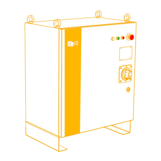
ARC5 series control cabinets - ARC5-12 and ARC5-25 ARC5-12/ARC5-25 control cabinet external interface instructions ARC5-12/ARC5-25 control cabinet external interface instructions Description of control cabinet indicator ARC5-12/ARC5-25 control cabinet provides three indicator lights, as shown in Figure 5-1, among which: ◼... -
Page 40: Functions Of Switches Inside The Control Cabinet
ARC5-12/ARC5-25 control cabinet external interface instructions ARC5 series control cabinets - ARC5-12 and ARC5-25 Figure 5-2 Power-on rotary switch Turn the switch to the "OPENRESET" position before opening the control cabinet door, otherwise the knob switch and circuit breaker will be damaged! Emergency stop button Press the emergency stop button and the robot will stop immediately (see Figure 5-1). -
Page 41: External Interface Of Control Cabinet
ARC5 series control cabinets - ARC5-12 and ARC5-25 ARC5-12/ARC5-25 control cabinet external interface instructions The ARC5-25 control cabinet provides three manual brake release buttons, which are used as follows: ◼ The ARC5-12 control cabinet only provides a manual brake release switch to control the brake release of all axes. -
Page 42: 24V Power Supply Module Inside The Control Cabinet
ARC5-12/ARC5-25 control cabinet external interface instructions ARC5 series control cabinets - ARC5-12 and ARC5-25 The control cabinet provides a teaching pendant installation interface, located above the left side of the front door of the control cabinet (see Figure 5-1). The teaching pendant interface is shown in Figure 5-4, and the pin number definition of the connector interface is detailed in Table 5-2. -
Page 43: Installation Of Internal Optional Accessories In The Control Cabinet
ARC5 series control cabinets - ARC5-12 and ARC5-25 ARC5-12/ARC5-25 control cabinet external interface instructions Figure 5-5 Diagram of switch power supply position Figure 5-6 Definition of switching power supply interface Installation of internal optional accessories in the control cabinet The ARC5-12/ARC5-25 control cabinet has reserved installation space for different optional modules, and customers can install the required optional components in the cabinet according to their needs. - Page 44 ARC5-12/ARC5-25 control cabinet external interface instructions ARC5 series control cabinets - ARC5-12 and ARC5-25 Figure 5-7 PEB module The installation and use of the PEB module refer to the content of the "PROFINET Communication Module" section in the "Installation and Use Manual for Optional Accessories" provided by Peitian.
- Page 45 ARC5 series control cabinets - ARC5-12 and ARC5-25 ARC5-12/ARC5-25 control cabinet external interface instructions Figure 5-8 External expansion PLC_ MF module The installation and use of the external expansion PLC_MF module refer to the content of the "External Expansion I/O Module" section in the "Installation and Use Manual for Optional Parts" provided by Peitian.
- Page 46 ARC5-12/ARC5-25 control cabinet external interface instructions ARC5 series control cabinets - ARC5-12 and ARC5-25 The installation and use of ARC5-12/ARC5-25 external expansion 48 channel IO module (NPN type) refer to the content of the "External Expansion I/O Module" section in the "Installation and Use Manual for Optional Parts"...
- Page 47 ARC5 series control cabinets - ARC5-12 and ARC5-25 ARC5-12/ARC5-25 control cabinet external interface instructions Figure 5-11 Guide rail mounting...
-
Page 49: Arc5-12/Arc5-25 Control Cabinet Hardware Module External Interface Description
ARC5-12/ARC5-25 control cabinet hardware module external ARC5 series control cabinets - ARC5-12 and ARC5-25 interface description ARC5-12/ARC5-25 control cabinet hardware module external interface description The ARC5-12/ARC5-25 control cabinet hardware module is located inside the control cabinet (refer to Figure 1-2 for location), providing some external interfaces for the control cabinet. -
Page 50: Safety Io Interface
ARC5-12/ARC5-25 control cabinet hardware module external interface description ARC5 series control cabinets - ARC5-12 and ARC5-25 Figure 6-3 Diagram of DCBS interface The names and functions of the external interfaces on the above hardware modules are detailed in Table 6-1. - Page 51 ARC5-12/ARC5-25 control cabinet hardware module external ARC5 series control cabinets - ARC5-12 and ARC5-25 interface description Figure 6-4 Safety IO interface pin identification diagram Table 6-2 Safety IO interface definition list Pin number Signal name Signal significance In/Out D+24V_EX 24V power supply...
-
Page 52: User Di Interface
ARC5-12/ARC5-25 control cabinet hardware module external interface description ARC5 series control cabinets - ARC5-12 and ARC5-25 Figure 6-5 Safety IO output signal User DI interface ARC5-12/ARC5-25 control cabinet provides users with 26 channels of DI, 2 channels of input common interface, and 4 channels of power interface. - Page 53 ARC5-12/ARC5-25 control cabinet hardware module external ARC5 series control cabinets - ARC5-12 and ARC5-25 interface description The wiring diagram and interface pin labels of the User DI interface are shown in Figure 6-6. The definition of the User DI interface is shown in Table 6-3, and the interface usage information is shown in Figure 6-7 and Figure 6-8.
- Page 54 ARC5-12/ARC5-25 control cabinet hardware module external interface description ARC5 series control cabinets - ARC5-12 and ARC5-25 Pin number Signal name Signal significance In/Out COM 1 DI1-13 input common terminal COM 2 DI14-26 input common terminal 24V power supply Power 24V power supply...
-
Page 55: User Do Interface
ARC5-12/ARC5-25 control cabinet hardware module external ARC5 series control cabinets - ARC5-12 and ARC5-25 interface description User DO interface The ARC5-12/ARC5-25 control cabinet provides users with 26 DO and 4 continuous current power interfaces. The User DO interface and pin labels are shown in Figure 6-9, and the definition of the User DO interface is detailed in Table 6-4. - Page 56 ARC5-12/ARC5-25 control cabinet hardware module external interface description ARC5 series control cabinets - ARC5-12 and ARC5-25 Pin number Signal name Signal significance In/Out DO 15 NPN digital output DO 16 NPN digital output DO 17 NPN digital output DO 18...
-
Page 57: User Serial Port Rs232 Interface
ARC5-12/ARC5-25 control cabinet hardware module external ARC5 series control cabinets - ARC5-12 and ARC5-25 interface description User serial port RS232 interface The ARC5-12/ARC5-25 control cabinet RS232 interface is an RS232 communication interface provided for users, and the RS232 interface is a plug-in terminal connector. -
Page 58: Plc-Rs485 Interface
ARC5-12/ARC5-25 control cabinet hardware module external interface description ARC5 series control cabinets - ARC5-12 and ARC5-25 Figure 6-12 MF-RS485 interface pin identification diagram Table 6-6 MF-RS485 interface definition list Interface Cable definition RS485_2_0_+ RS485_2_0_- GND_ISO_RDC MF-RS485 interface CHGND_1 120Ω resistor short contact 1 120Ω... -
Page 59: User Ethernet Port
ARC5-12/ARC5-25 control cabinet hardware module external ARC5 series control cabinets - ARC5-12 and ARC5-25 interface description Table 6-7 PLC-RS485 interface definition list Interface Cable definition RS485_1_0_+ RS485_1_0_- GND_ISO_MF PLC-RS485 interface CHGND_1 120Ω resistor short contact 1 120Ω resistor short contact 2... -
Page 61: Arc5-12/Arc5-25 Control Cabinet Maintenance And Fault Handling
ARC5 series control cabinets - ARC5-12 and ARC5-25 ARC5-12/ARC5-25 control cabinet maintenance and fault handling ARC5-12/ARC5-25 control cabinet maintenance and fault handling Routine maintenance items and cycles The multi axis drive debugging interface for ARC5-12/ARC5-25 control cabinet is located inside the front door brake box at the back of the control cabinet. - Page 62 ARC5-12/ARC5-25 control cabinet maintenance and fault handling ARC5 series control cabinets - ARC5-12 and ARC5-25 Dust screen replacement The ARC5-12/ARC5-25 control cabinet is equipped with three dust screens installed at the left and right air ducts of the transformer under the rear door components and cabinet body, as shown in Figure 7-2. Under normal use, the dust screens of the control cabinet should be cleaned every three months and replaced every other year;...
-
Page 63: Possible Troubleshooting Steps
ARC5 series control cabinets - ARC5-12 and ARC5-25 ARC5-12/ARC5-25 control cabinet maintenance and fault handling Installation steps for dust screen: Possible troubleshooting steps Circuit breaker and contactor When the circuit breaker and other operating reset mechanisms cannot be flexibly switched on or off or the appearance is damaged and carbonized, they should be replaced immediately. - Page 64 ARC5-12/ARC5-25 control cabinet maintenance and fault handling ARC5 series control cabinets - ARC5-12 and ARC5-25 Fuse When the power indicator light of the control cabinet is on, but some electrical components cannot be powered on, please check whether the corresponding fuse on the adapter board is burnt out. If there is a burn out situation, please replace the fuse according to Table 7-2.
-
Page 65: Arc5-12/Arc5-25 Control Cabinet Storage Conditions
ARC5 series control cabinets - ARC5-12 and ARC5-25 ARC5-12/ARC5-25 control cabinet storage conditions ARC5-12/ARC5-25 control cabinet storage conditions During long-term storage, the control cabinet shall be placed in a cool and waterproof place away from direct sunlight. The specific environmental requirements are shown in Table 8-1:... -
Page 67: Appendix A Arc5-12/Arc5-25 Accessories List
ARC5 series control cabinets - ARC5-12 and ARC5-25 Appendix A ARC5-12/ARC5-25 accessories list Appendix A ARC5-12/ARC5-25 accessories list Schedule 1 ARC5-12/ARC5-25 control cabinet cable accessories list Corresponding Accessory Name Part number Accessory Properties interface ARC5-12 standard (5 meters in inCube20- Heavy load harness outside the cabinet... -
Page 69: Appendix B Arc5-12/Arc5-25 Accessories Description
ARC5 series control cabinets - ARC5-12 and ARC5-25 Appendix B ARC5-12/ARC5-25 accessories description Appendix B ARC5-12/ARC5-25 accessories description External wiring for heavy-duty interfaces The basic specifications and installation methods of external wiring for heavy-duty interfaces are detailed in Schedule 2 and Schedule 3. - Page 70 Appendix B ARC5-12/ARC5-25 accessories description ARC5 series control cabinets - ARC5-12 and ARC5-25 Refer to Chapter 5.4 for the definition of the teaching pendant interface end 提示 External wiring of power interface The basic specifications and installation methods of the power wire harness corresponding to ARC5-12 and ARC5-25 are detailed in Figure 3-6 and Table3-6 in Chapter 3.3.
- Page 71 ARC5 series control cabinets - ARC5-12 and ARC5-25 Appendix B ARC5-12/ARC5-25 accessories description ◼ The connector wire sequence at both ends of the inCube20 user DI terminal module cable corresponds one-to-one with the number tube label. ◼ The cable number of the inCube20 user DI terminal module corresponds one-to-one with the control cabinet and User DI interface number.
- Page 72 Appendix B ARC5-12/ARC5-25 accessories description ARC5 series control cabinets - ARC5-12 and ARC5-25 EtherCAT interface external cable The basic specifications of industrial network cables are the same as Schedule 8. Servo Debugger external wiring The basic specifications of the USB to RS422/RS485 cable are detailed in Schedule 10.
- Page 73 ARC5 series control cabinets - ARC5-12 and ARC5-25 Appendix B ARC5-12/ARC5-25 accessories description B-end European terminals C0.5-8 connector Cable 10CX0.2mm² Length 5 meters J6\J7 interface external wiring The basic specifications of the shared wiring harness between the magnetic grating ruler and the CAN_ encoder are detailed in Schedule 14.
- Page 74 Appendix B ARC5-12/ARC5-25 accessories description ARC5 series control cabinets - ARC5-12 and ARC5-25 Incoming cable part Cable threading Name of incoming cable Introducing Cable Properties Cable core model number part number SCRC10- RS485 wiring Optional (outer diameter P04082000844 P01055001548 harness outside the cabinet...
- Page 75 ARC5 series control cabinets - ARC5-12 and ARC5-25 Appendix B ARC5-12/ARC5-25 accessories description Figure1 Use of cable entry In addition to the single core cables provided in Schedule 15, customers can also combine different specifications of cable cores according to the actual cable outer diameter and quantity used. If there are many cables introduced, a set of cable entry components can also be added in the reserved position.
- Page 76 Appendix B ARC5-12/ARC5-25 accessories description ARC5 series control cabinets - ARC5-12 and ARC5-25 Name Cable core model Cable threading part number Specifications Small cable threading KT2/3 P01055001629 Outer diameter 2xφ3mm Small cable threading KT2/4 P01055001630 Outer diameter 2xφ4mm Small cable threading...
- Page 77 ARC5 series control cabinets - ARC5-12 and ARC5-25 Appendix B ARC5-12/ARC5-25 accessories description...
Need help?
Do you have a question about the ARC5 Series and is the answer not in the manual?
Questions and answers