Table of Contents
Advertisement
Quick Links
Advertisement
Table of Contents

Related Manuals for PEITIAN ROBOTICS ARC4-165


Summary of Contents for PEITIAN ROBOTICS ARC4-165
- Page 1 V1.2.1...
-
Page 3: Introduction
ARC4-165 Control Cabinet Manual Introduction Introduction About this manual This manual is for technicians to quickly, correctly and safely install and use the ARC4- 165 control cabinet, familiarize themselves with relevant precautions and do regular routine maintenance of the control cabinet. - Page 4 Introduction ARC4-165 Control Cabinet Manual Sign Meaning You are prompted to refer to other documents and instructions for additional information or more detailed operating instructions 提示 Manual description The content of this manual will be supplemented and modified. Please pay attention to the "Download"...
- Page 5 ARC4-165 Control Cabinet Manual Introduction Table 4 Declaration of applicable safety standards Standard Description Version Machinery directive: Machinery Directive 2006/42/EC (new edition) 2006/42/EC 2006 released by the European Parliament and Council on May 17, 2006, including changes to 95/16/EC EMC directive:...
-
Page 7: General Safety Instructions
ARC4-165 Control Cabinet Manual General safety instructions General safety instructions Thanks very much for your purchase of the manipulator made by the company. The information described is necessary for safely using the manipulator. Please read associated manual carefully before using the manipulator, and properly use it under the premise of understanding its contents. - Page 8 General safety instructions ARC4-165 Control Cabinet Manual Use in explosive environment Use in environments with a lot of radiation Use in water or high humidity environment Use for the purpose of transporting people or animals. Use as a tripod (such as climbing on top of the ...
- Page 9 ARC4-165 Control Cabinet Manual General safety instructions Carefully view the conditions in the safety barrier, and then enter the barrier after ensuring there is no danger; Make sure the emergency stop button can be pressed at any time;...
- Page 10 General safety instructions ARC4-165 Control Cabinet Manual If customers replace the parts by themselves, unexpected accidents may occur, and then it will cause damage and injury to the manipulator and operating personnel respectively. When entering into the safety barrier, the whole system ...
- Page 11 ARC4-165 Control Cabinet Manual General safety instructions Testing and operation shall be carried out in accordance with prescribed methods after components replacement. At this moment, the operating personnel shall operate outside the safety barrier. After maintenance ends, lubricating oil, debris, water, etc.
-
Page 13: Safety Precautions
ARC4-165 Control Cabinet Manual Safety precautions Safety precautions Before operating the manipulator, peripheral equipment and its manipulator system, sufficiently study the safety precaution for operating personnel and system. Figure 1 is a diagram of the safe work of industrial robots. - Page 14 Safety precautions ARC4-165 Control Cabinet Manual The manipulator can be maintained (repair, adjustment, replacement, etc.) operations. Safety of operating personnel When operating, programming, and maintaining the manipulator, operators, instructors, and maintenance engineers must pay attention to safety and at least wear the following items for work: Appropriate working clothes;...
- Page 15 ARC4-165 Control Cabinet Manual Safety precautions When taking single commissioning of peripheral equipment, the manipulator power shall be disconnected. The safety of operator Operator is not entitled to operate in the safety barriers: If the manipulator motion is not required, its control cabinet power shall be ...
- Page 16 Safety precautions ARC4-165 Control Cabinet Manual Programmer shall evacuate to the outer place of the safety barrier during automatic operation of the manipulator. The safety of maintenance engineer To ensure the safety of maintenance engineer, the following items shall be fully noticed: During the manipulator operation, don't enter into its motion range;...
- Page 17 ARC4-165 Control Cabinet Manual Safety precautions Fully ensure that there is no one within operation scope of the manipulator and the manipulator and peripheral equipment are in good conditions when restarting the manipulator system after the maintenance. Safety of peripheral equipment Attentions on relevant program Checkout equipment such as limit switch, etc.
- Page 18 Safety precautions ARC4-165 Control Cabinet Manual Mutual interference between manipulators shall be fully avoided during operational scope from multiple manipulators. Set a specified work origin for manipulator program and create a program starting from work origin and ending at this one to see clearly whether operation of the manipulator is finished or not from the outer edge.
-
Page 19: Table Of Contents
Safe use of ARC4-165 control cabinet ....................17 Grounding of control cabinet ....................... 17 Robot stop mode ..........................17 ARC4-165 control cabinet interface and indicator light instructions ..........19 Control cabinet indicator light description ..................19 Functions of switches outside the control cabinet ................19 Functions of switches inside the control cabinet ................. -
Page 21: Overview Of Arc4-165 Control Cabinet
ARC4-165 Control Cabinet Manual Overview of ARC4-165 control cabinet Overview of ARC4-165 control cabinet Overview of industrial robot The industrial robot is composed of the following components: Manipulator Control cabinet Teach pendant Connection (power supply) cables, etc. -
Page 22: Basic Composition Of Control Cabinet
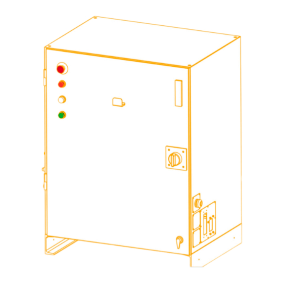
Overview of ARC4-165 control cabinet ARC4-165 Control Cabinet Manual Figure 1-2 Control cabinet appearance Teach pendant The teach pendant is connected to the master control system of the robot's control cabinet. It is used to remotely control the robot to run manually and automatically, record the running trajectory, display playback or record teach points and program according to the teach points. -
Page 23: Control Cabinet Characteristics
The top of the control cabinet can withstand an average load of 1000N. Control cabinet labels and their meanings ARC4-165 type control cabinet contains five kinds of labels. Refer to Figure 1-4 for the specific location of each label. - Page 24 Overview of ARC4-165 control cabinet ARC4-165 Control Cabinet Manual Figure 1-4 Location diagram of labels contained in control cabinet Pairing information indicator The pairing information indicator is shown in Figure 1-5.
- Page 25 ARC4-165 Control Cabinet Manual Overview of ARC4-165 control cabinet Figure 1-5 Pairing information indicator Door opening and power-off & maintenance indicator The door opening and power-off & maintenance indicator is shown in Figure 1-6. Figure 1-6 Door opening and power-off & maintenance indicator High temperature sign The place with high temperature sign (Figure 1-7) may get hot again.
-
Page 26: Installation Environment Of Control Cabinet
Overview of ARC4-165 control cabinet ARC4-165 Control Cabinet Manual Figure 1-8 Electric shock sign Nameplate of control cabinet The nameplate of the control cabinet is shown in Figure 1-9. The nameplate indicates the model, serial number, weight, production date and other relevant information of the control cabinet (the parameters are subject to the actual object). - Page 27 ARC4-165 Control Cabinet Manual Overview of ARC4-165 control cabinet The control cabinet can work normally when the altitude is ≤ 1000m. Please consult our company when using at an altitude higher than 1000 meters. The control cabinet can work normally under the atmospheric pressure of 86kPa ~106kPa.
-
Page 29: Arc4-165 Control Cabinet Transportation And Handling
ARC4-165 Control Cabinet Manual ARC4-165 control cabinet transportation and handling ARC4-165 control cabinet transportation and handling Four M12 lifting screws are provided above the control cabinet, as shown in Figure 2-1. Four lifting rings can be used for lifting and handling. -
Page 31: Installation And Connection Of Arc4-165 Control Cabinet
Definition of control cabinet electrical connection Definition of power line interface for heavy-duty plugs in control cabinets The definition of the power line interface for the heavy-duty plug of the ARC4-165 control cabinet is shown in Figure 3-1. Figure 3-1 ARC4-165 control cabinet heavy-duty control cabinet power line interface The definition of the power line interface for the heavy-duty plug of ARC4-165 control cabinet is detailed in Table 3-1. - Page 32 Brake line -6 axis b-13 57,58,59 5 axis -U5 a-12 YB6+ b-14 60,61,62 5 axis -V5 Brake line -6 axis YB6- Control cabinet heavy-duty (Encoder) interface definition The interface definition of ARC4-165 control cabinet heavy-duty (encoder) is shown in Figure 3-2.
- Page 33 Installation and connection of ARC4-165 control cabinet Figure 3-2 ARC4-165 control cabinet heavy-duty (encoder) interface definition The definition of the encoder line interface for ARC4-165 control cabinet is detailed in Table 3-2. Table 3-2 Encoder line interface definition Signal name...
- Page 34 Installation and connection of ARC4-165 control cabinet ARC4-165 Control Cabinet Manual Signal name Axis number Pin number Signal name Axis number Pin number 4 axis 4 axis Encoder wire specifications and joint size instructions Figure 3-3 Diagram of ARC4-165 encoder line...
- Page 35 ARC4-165 Control Cabinet Manual Installation and connection of ARC4-165 control cabinet Power line specifications and joint size instructions Figure 3-5 ARC4-165 power line diagram Table 3-5 ARC4-165 power line specification table A-end B-end Wire diameter Wire diameter Minimum Name connection form...
-
Page 36: Connection Method Between Control Cabinet And Manipulator
Connection method between control cabinet and manipulator The ARC4-165 control cabinet has 3 external cables, 2 of which are connected to the manipulator, and 1 of which is a 4-core main power cable connected to the power supply. The power cord specifications are shown in Table 3-7. -
Page 37: Safe Use Of Arc4-165 Control Cabinet
The ARC4-165 control cabinet is grounded through the PE pin in the power cord entrance. It must be ensured that the cable input end connected to the control cabinet has a reliable ground connection. Under normal circumstances, the resistance between the cable input end PE and the earth is required to be no greater than 100Ω... -
Page 39: Arc4-165 Control Cabinet Interface And Indicator Light Instructions
ARC4-165 control cabinet interface and indicator light instructions Control cabinet indicator light description ARC4-165 control cabinet provides three indicator lights, as shown in Figure 5-1, among which: The white power indicator light of the control cabinet lights up when the control cabinet is started. -
Page 40: Functions Of Switches Inside The Control Cabinet
ARC4-165 control cabinet interface and indicator light instructions ARC4-165 Control Cabinet Manual Figure 5-2 Power-on rotary switch Turn the switch to the "OPENRESET" position before opening the control cabinet door, otherwise the knob switch and circuit breaker will be damaged! Emergency stop button Press the emergency stop button and the robot will stop immediately (see Figure 5-1). -
Page 41: External Interface Of Control Cabinet
ARC4-165 Control Cabinet Manual ARC4-165 control cabinet interface and indicator light instructions Figure 5-3 Manual brake release interface description When using the manual brake release function, please be aware that the corresponding axis may suddenly fall under the action of gravity, and auxiliary support and personnel safety issues must be considered in advance. - Page 42 ARC4-165 control cabinet interface and indicator light instructions ARC4-165 Control Cabinet Manual Figure 5-4 Teach pendant connector In addition to the teach pendant interface, the control cabinet also provides 2 heavy-duty connector interfaces, namely the motor power and brake cable interface and the encoder interface, as well as 1 external power input...
- Page 43 ARC4-165 Control Cabinet Manual ARC4-165 control cabinet interface and indicator light instructions Figure 5-5 ARC4-165 control cabinet external cable The power and brake heavy-duty wires and the encoder heavy-duty cables are divided into cabinet wire harnesses and cabinet external cable harnesses. The material numbers and specifications of each cable harness are shown in Table 5-1.
-
Page 45: Introduction To Arc4-165 Control Cabinet Hardware Modules
ARC4-165 Control Cabinet Manual Introduction to ARC4-165 control cabinet hardware modules Introduction to ARC4-165 control cabinet hardware modules PLC_MF Definition of each port PLC_MF is used for communication with external devices. As shown in Figure 6-1. Figure 6-1 PLC_MF Station address dial switch S2 high position. - Page 46 Introduction to ARC4-165 control cabinet hardware modules ARC4-165 Control Cabinet Manual Figure 6-2 DI port number DO port connector The DO port connector number is shown in Figure 6-3. Figure 6-3 DO port number If you need to control the body IO through PLC_MF, you can connect the unconnected IO cables in the encoder harness inside the cabinet according to the label content of the cable identification tube to the corresponding pins on the DI and DO interfaces of PLC_MF.
-
Page 47: Plc_Int
ARC4-165 Control Cabinet Manual Introduction to ARC4-165 control cabinet hardware modules Table 6-1 PLC_MF baud rate setting DIP switch points Baud rate DIP switch points Baud rate 1200 56000 2400 57600 4800 115200 9600 230400 14400 460800 19200 921600 38400... - Page 48 Introduction to ARC4-165 control cabinet hardware modules ARC4-165 Control Cabinet Manual Signal name Signal name number number drive 1) (Drive 1 Brake Signal/Input) COMMON_MOTOR/GND DI_MOTOR2 (Common terminal for brake signal of (Drive 2 Brake Signal/Input) drive 2) COMMON_MOTOR/GND DI_MOTOR3 (Common terminal for brake signal of...
- Page 49 ARC4-165 Control Cabinet Manual Introduction to ARC4-165 control cabinet hardware modules Signal name Signal name number number DGND_IO DO_SAFE_RESET_N (Signal ground) (SAF module reset signal negative/output) DO_CTR_STATE_N DO_SAFE_RESET_P (SAF module control signal (SAF module reset signal positive/output) negative/output) DO_CTR_STATE_P DO_CONTACTOR2...
- Page 50 Introduction to ARC4-165 control cabinet hardware modules ARC4-165 Control Cabinet Manual Signal name Signal name number number (Panel signal 1 corresponds to ground) (Panel signal 1/output) DO_RESERVE4/GND DO_RESERVE4 (Digital signal 4 corresponds to ground) (Digital signal 4/output) DO_RESERVE3/GND DO_RESERVE3 (Digital signal 3 corresponds to ground)
-
Page 51: Security Module
ARC4-165 Control Cabinet Manual Introduction to ARC4-165 control cabinet hardware modules Signal name Signal name number number COMMON_PANEL/+24V DI_PANEL2 (Signal common ground) (Panel Signal 2/Input) COMMON_DOOR/+24V DI_DOOR (Common terminal for cabinet door (Cabinet door switch status signal/input) switch status signal) - Page 52 Introduction to ARC4-165 control cabinet hardware modules ARC4-165 Control Cabinet Manual Figure 6-5 Security module Safety module internal PLC Connector (X1) definition The definition of the internal PLC connector (X1) in the safety module is detailed in Table 6-10. Table 6-10 Definition of safety module internal PLC connector (X1)
- Page 53 ARC4-165 Control Cabinet Manual Introduction to ARC4-165 control cabinet hardware modules Signal name Pin number Signal name number (External safety signal 2-) (External safety signal 2+) EXT_SAFE1- EXT_SAFE1+ (External Safety Signal 1-) (External safety signal 1+) AC220_L AC220_N (220V positive)
-
Page 54: Mcb Module
Introduction to ARC4-165 control cabinet hardware modules ARC4-165 Control Cabinet Manual Signal name Pin number Signal name number COMMON_ALARM COMMON_ALARM (Driver alarm input ground) (Driver alarm input ground) DI_KEY_EN COMMON_KEY_EN (Teach pendant key signal input) (Teach pendant key signal input ground) - Page 55 ARC4-165 Control Cabinet Manual Introduction to ARC4-165 control cabinet hardware modules MANUAL_ PowerDown MCB module connector (X2) definition The definition of MCB module connector (X2) is detailed in Table 6-15. Table 6-15 MCB module connector (X2) definition Pin number Signal name...
-
Page 57: Arc4-165 Control Cabinet Maintenance And Fault Handling
ARC4-165 control cabinet maintenance and fault handling ARC4-165 control cabinet maintenance and fault handling Routine maintenance items and cycles The routine maintenance items and cycles of the ARC4-165 control cabinet are detailed in Table 7-1. Table 7-1 Routine maintenance items and cycles Maintenance project... - Page 58 ARC4-165 control cabinet maintenance and fault handling ARC4-165 Control Cabinet Manual Indicator light When the indicator light or other indicating device fails to emit signals normally, first check if the connecting circuit is faulty; if the circuit is fine, then replace the indicating device and observe if it can emit signals normally.
- Page 59 ARC4-165 Control Cabinet Manual ARC4-165 control cabinet maintenance and fault handling Corresponding Fuse Function Specifications terminal X251,X252 Protect 220V backup power supply 1.6A Protect 220V to 24V power module 2 0.8A Protect other 24VDC power supplies Protect the output power of the holding brake Common alarms and corresponding solutions for drivers For common alarms and their handling, please refer to Table 7-3 in the manual.
- Page 60 ARC4-165 control cabinet maintenance and fault handling ARC4-165 Control Cabinet Manual Alarm code Alarm name Solution Check if shielded ethernet cable is used, and if the Er405 Bus UpdateCnt error communication is disconnected Er410 Bus signal synchronization error Restart Er504...
- Page 61 ARC4-165 Control Cabinet Manual ARC4-165 control cabinet maintenance and fault handling Alarm code Alarm name Solution Er832 Encoder overheating Check the encoder heat dissipation environment Er833 Encoder battery voltage alarm Check encoder battery voltage Er834 Encoder battery voltage fault Check encoder battery voltage...
- Page 62 ARC4-165 control cabinet maintenance and fault handling ARC4-165 Control Cabinet Manual Ca516 Regeneration overload warning Check for regeneration overload...
-
Page 63: Arc4-165 Control Cabinet Storage Conditions
ARC4-165 Control Cabinet Manual ARC4-165 control cabinet storage conditions ARC4-165 control cabinet storage conditions During long-term storage, the control cabinet shall be placed in a cool and waterproof place away from direct sunlight. The specific environmental requirements are shown in Table 8-1:... - Page 64 ARC4-165 control cabinet storage conditions ARC4-165 Control Cabinet Manual...
Need help?
Do you have a question about the ARC4-165 and is the answer not in the manual?
Questions and answers