Table of Contents
Advertisement
48VG ---A and 48VG ---E
Performancet 15---16 SEER 2---Stage Packaged Air
Conditioner and Gas Furnace System with Puron
(R ---410A) Refrigerant
Single and Three Phase
2---5 Nominal Tons (Sizes 24---60)
IMPORTANT: Effective January 1, 2015, all split system and
packaged air conditioners must be installed pursuant to applicable
regional efficiency standards issued by the Department of Energy.
NOTE:
Read the entire instruction manual before starting the
installation.
NOTE:
Installer: Make sure the Owner's Manual and Service
Instructions are left with the unit after installation.
TABLE OF CONTENTS
. . . . . . . . . . . . . . . . . . . . . . . . . . . . . . . . . . .
. . . . . . . . . . . . . . . . . . . . . . . . . . . . . . . . . .
. . . . . . . . . . . . . . . . . . . . . . . . . . . . . . . . . . . .
. . . . . . . . . . . . . . . . . . . . . . . . . . . . . . . . .
. . . . . . . . . . . . . . . . . . . . . . . . . . . . . . .
. . . . . . . . . . . . . . . . . . . . . . . . . . . . . . . . . . . . . .
. . . . . . . . . . . . . . . . . . . . . . . . . . . . . . . . . . . . .
. . . . . . . . . . . . . . . . . . . . . . . . . . . .
. . . . . . . . . . . . . . . . . . . . . . . . . . . . . . . . .
. . . . . . . . . . . . . . . . . . . . . . . . . . . . . . . . .
. . . . . . . . . . . . . . . . . . . . . . . . . . . . . . . . . . . . . .
. . . . . . . . . . . . . . . . . . . . . . . . . . . .
. . . . . . . . . . . . . . . . . . . . . . . . . . . . . . . . . .
. . . . . . . . . . . . . . . . . . . . . . . . . . . . . . . . .
. . . . . . . . . . . . . . . . . . . . . . . . . . . .
. . . . . . . . . . . . . . . . . . . . . . . . . . . . . . . . . . . . .
. . . . . . . . . . . . . . . . . . . . . . . . . . . . .
. . . . . . . . . . . . . . . . . . . . . . . . . . .
. . . . . . . . . . . . . . . . . . . . . . . . . . . . . . . . . . .
. . . . . . . . . . . . . . . . . . . . . . . . . . . . . . . . . . . . .
. . . . . . . . . . . . . . . . . . . . . . . . . . .
. . . . . . . . . . . . . . . . . . . . . . . . . . . . . . . .
. . . . . . . . . . . . . . . . . . . . . . . . . . . . . . . .
. . . . . . . . . . . . . . . . . . . . . . . . . . . . .
. . . . . . . . . . . . . . . . . . . . . . . . . . . . . . .
. . . . . . . . . . . . . . . . . . . . . . . . . . . . . . . . .
. . . . . . . . . . . . . . . . . . . . . . . . . . . . . . . . .
Installation Instructions
. . . . . . . . . . . . . . . . . . . . . . . . .
. . . . . . . . . . . . . . . . .
. . . . . . . . . . . . . . . . . . . . . . . . . .
. . . . . . . . . . . . . . . . . . . . . . . .
. . . . . . . . . . . . . . . . . . . . . . . .
. . . . . . . . . . . . . .
. . . . . . . . . . . . . . . . . . . . . . .
. . . . . . . . . . . . . . . . . . . . . . . . . .
. . . . . . . . . . . . . . . . . . . . . . . . .
. . . . . . . . . . . . . . . .
. . . . . . . . . . . . . . . . . . . . . .
. . . . . . . . . . . . . . . . . . . . .
. . . . . . . . . . . . . . . .
. . . . . . . . . . . . . . . .
. . . . . . . . . . . .
. . . . . . . . . . . . .
. . . . . . . . . . . . . . . . . . . . .
PAGE
1
2
2- -14
2
2
2
2
2
. . . . . . . . . . . . . . . . . . . . . . . . . . . . . . . . . . . . . .
3
3
3
3
3
3
10
10
11
12
12
. . . . . . . . . . . . . . . . . . . . . . . . . . . . . . . . . . . . . .
13
13
13
13
14
SAFETY CONSIDERATIONS
14
14
Improper installation, adjustment, alteration, service maintenance,
14
or use can cause explosion, fire, electrical shock, or other
15- -30
conditions which may cause death, personal injury, or property
15
damage. Consult a qualified installer, service agency, or your
15
distributor or branch for information or assistance. The qualified
15
installer or agency must use factory- -authorized kits or accessories
16
when modifying this product. Refer to the individual instructions
16
packaged with the kits or accessories when installing.
18
Follow all safety codes. Wear safety glasses, protective clothing,
28
and work gloves. Have a fire extinguisher available. Read these
28
instructions thoroughly and follow all warnings or cautions
28
included in literature and attached to the unit. consult local
28
building codes, the current editions of the National Fuel Gas Code
28
(NFGC) NFPA 54/ANSI Z223.1, and the National Electrical Code
28
(NEC) NFPA 70.
28
In Canada refer to the current editions of the National Standards of
29
Canada CAN/CSA- -B149.1 and .2 Natural Gas and Propane
29
Installation codes, and Canadian Electrical Code CSA C22.1
30
1
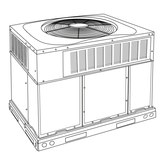
Fig. 1 - - Unit 48VG
(Low NOx Model Available)
. . . . . . . . . . . . . . . . . . . . . . . . . . . . . . . .
. . . . . . . . . . . . . . . . . . . . . . . . .
. . . . . . . . . . . . . .
. . . . . . . . . . . . . . . . . . . . . . . . . . . .
. . . . . . . . . . . . . . . . . . . . . . . . . . . . . . . . . . .
. . . . . . . . . . . . . . . . . . . . . . . . . . . . . . . . .
. . . . . . . . . . . . . . . . . . . . . . . . . . . . . . . . . . .
. . . . . . . . . . . . . . . . . . . . . . . . . . . .
. . . . . . . . . . . . . . . . . . . . . . . . . . . . . . . . . . .
. . . . . . . . . . . . . . . . . . . . .
. . . . . . . . . . . . . . . . . . . . . . . . . . . . . . .
. . . . . . . . . . . . . . . . . . . . . . . . . . . . . .
. . . . . . . . . . . . . . . . . . . . . . . . . . . . . . . . . . . .
. . . . . . . . . . . . . . . . . . . . . . . . . . . . . .
. . . . . . . . . . . . . . . . . . . . . . . . . . . .
A09033
65- -68
65
65
66
66
66
66
66
66
. . . .
66
67
67
68
68
68
68
69
69
Advertisement
Table of Contents

Related Manuals for Carrier Performance 48VG-E


Summary of Contents for Carrier Performance 48VG-E
-
Page 1: Table Of Contents
48VG ---A and 48VG ---E Performancet 15---16 SEER 2---Stage Packaged Air Conditioner and Gas Furnace System with Puron (R ---410A) Refrigerant Single and Three Phase 2---5 Nominal Tons (Sizes 24---60) Installation Instructions IMPORTANT: Effective January 1, 2015, all split system and packaged air conditioners must be installed pursuant to applicable regional efficiency standards issued by the Department of Energy. -
Page 2: Introduction
a rooftop or on a cement slab. (See Fig. 5 for roof curb Recognize safety information. This is the safety- -alert symbol dimensions). When you see this symbol on the unit and in instructions or manu- In gas heating mode, this unit is designed for a minimum als, be alert to the potential for personal injury. -
Page 3: Slab Mount
Do not place the unit where water, ice, or snow from an overhang WARNING or roof will damage or flood the unit. Do not install the unit on carpeting or other combustible materials. Slab- -mounted units should be at least 2 in. (51 mm) above the highest expected water UNITS/STRUCTURAL DAMAGE HAZARD and runoff levels. - Page 4 2. Attach shackles, clevis pins, and straps to the base rails of the unit. Be sure materials are rated to hold the weight of the unit (See Fig. 6). 3. Attach a clevis of sufficient strength in the middle of the straps.
- Page 5 A190129 Fig. 3 - - 48VG 24- -30 Unit Dimensions...
- Page 6 A190130 Fig. 4 - - 48VG 36- -60 Unit Dimensions...
- Page 7 SMALL/COMMON CURB SMALL SUPPLY BASE UNIT LARGE BASE RETURN UNIT UNIT PLACEMENT ON COMMON CURB SMALL OR LARGE BASE UNIT LARGE CURB A180216 B (small / common B (large UNIT CATALOG base) base) SIZE NUMBER IN. (mm) IN. (mm) (mm) IN.
- Page 8 CAUTION - NOTICE TO RIGGERS PRUDENCE - AVIS AUX MANIPULATEUR ACCESS PANELS MUST BE IN PLACE WHEN RIGGING. PANNEAUX D'ACCES DOIT ÊTRE EN PLACE POUR MANIPULATION. Use top skid as spreader bar. / Utiliser la palette du haut comme barre de répartition DUCTS MINIMUM HEIGHT: 36"...
- Page 9 Table 1 – Physical Data UNIT SIZE 24040 24060 30040 30060 36060 36090 42060 42090 NOMINAL CAPACITY (ton) 2 ---1/2 2 ---1/2 3 ---1/2 3 ---1/2 SHIPPING WEIGHT** lb. SHIPPING WEIGHT** (kg) Scroll COMPRESSORS Quantity REFRIGERANT (R --- 410A) Quantity lb. Quantity (kg) REFRIGERANT METERING DEVICE OUTDOOR COIL...
-
Page 10: Connect Condensate Drain
Table 1—Physical Data Con’t UNIT SIZE 48090 48115 48130 60090 60115 60130 NOMINAL CAPACITY (ton) SHIPPING WEIGHT lb SHIPPING WEIGHT kg Scroll COMPRESSORS Quantity REFRIGERANT (R --- 410A) 10.8 10.8 10.8 12.1 12.1 12.1 Quantity lb Quantity (kg.) REFRIGERANT METERING DEVICE OUTDOOR COIL Rows...Fins/in. -
Page 11: Install Gas Piping
2. Remove flue hood from shipping location (inside the return 2. Protect all segments of piping system against physical and section of the blower compartment- -see Fig. 9). Remove the thermal damage. Support all piping with appropriate straps, return duct cover to locate the flue hood. Place flue hood hangers, etc. -
Page 12: Install Duct Connections
tion, and only the piece over the downshot knockout needs WARNING to be removed. Discard insulation. 4. To remove the downshot (plastic) knockouts for both sup- FIRE OR EXPLOSION HAZARD ply and returns, break front and right side connecting tabs with a screwdriver and hammer. -
Page 13: Install Electrical Connections
5. Size all ductwork for maximum required airflow (either codes for maximum fuse/circuit breaker size and minimum circuit heating or cooling) for unit being installed. Avoid abrupt amps (ampacity) for wire sizing. duct size increases or decreases or performance may be The field- -supplied disconnect switch box may be mounted on the affected. -
Page 14: Standard Connection
Standard Connection PRE- - START- - UP Run the low- -voltage leads from the thermostat, through the inlet WARNING hole, and into unit low- -voltage splice box. Locate eight (six for 460V 3- -phase) 18- -gage wires leaving control box. These low- -voltage connection leads can be identified ENVIRONMENTAL, FIRE, EXPLOSION,... -
Page 15: Check For Refrigerant Leaks
Step 2 — Start- -up Heating and Make Adjust- WARNING ments Complete the required procedures given in the Pre- -Start- -Up FIRE, EXPLOSION HAZARD section before starting the unit. Do not jumper any safety devices Failure to follow this warning could result in personal when operating the unit. -
Page 16: Check Gas Input
5. Once flame is established the integrated gas unit controller Table 3 – Altitude Derate Multiplier for U.S.A.* (IGC) will look for 24- -v power to W1 and W2. If there is DERATE MULTIPLIER ALTITUDE FT (M) PERCENT OF DERATE 24- -v power to W1 only, the IGC will switch the induced- - FACTOR{ draft motor down to low speed and maintain low stage on... - Page 17 Table 4 – Natural Gas Orifice Sizes and Manifold Pressure 208/230VAC Models ALTITUDE OF INSTALLATION (FT. [m] ABOVE SEA LEVEL) U.S.A.* Nameplate 2001 to 3001 to 4001 to 5001 to Input, 0 to 2000 3000* 4000 5000 6000 High Stage [610 to [915 to [1220 to...
-
Page 18: Check Burner Flame
2. 3600 32 = 112.5. REGULATOR COVER SCREW 3. 112.5 x 1 =112.5 ft of gas flow/hr. PLASTIC ADJUST SCREW 4. 112.5 x 1050 = 118,125 Btuh input. ON/OFF SWITCH REGULATOR SPRING If the desired gas input is 115,000 Btuh, only a minor change in the manifold pressure is required. - Page 19 Table 6 – Heating Inputs 208/230 VAC Models GAS SUPPLY PRESSURE (IN. W.C.) MANIFOLD PRESSURE MANIFOLD PRESSURE HEATING INPUT NUMBER OF NUMBER OF (IN. W.C.) Natural{ Propane*{ (BTUH) ORIFICES ORIFICES Natural{ Propane*† 40,000 13.0 11.0 13.0 3.23.8 10.0 60,000 13.0 11.0 13.0 3.23.8...
- Page 20 A14593 Fig. 15 - - 208/230- -1- -60 Connection Wiring Diagram...
- Page 21 A14594 Fig. 17 Cont. - - 208/230- -1- -60 Ladder Wiring Diagram...
- Page 22 A14615 Fig. 16 - - 208/230- -3- -60 Connection Wiring Diagram Gas Inputs 40, 60, 90 KBtu/hr...
- Page 23 A14616 Fig. 18 Cont. - - 208/230- -3- -60 Ladder Wiring Diagram Gas Inputs 40, 60, 90 KBtu/hr...
- Page 24 A14618 Fig. 17 - - 208/230- -3- -60 Connection Wiring Diagram Gas Inputs 115, 130...
- Page 25 A14617 Fig. 19 Cont. - - 208/230- -3- -60 Ladder Wiring Diagram Gas Inputs 115, 130...
- Page 26 A13026 Fig. 18 - - 460- -3- -60 Connection Wiring Diagram...
- Page 27 A13027 Fig. 20 Cont.- - 460- -3- -60 Ladder Wiring Diagram...
-
Page 28: Normal Operation
Normal Operation Table 8 – LED Indications STATUS CODE LED INDICATION An LED (light- -emitting diode) indicator is provided on the Normal Operation integrated gas unit controller (IGC) to monitor operation. The IGC No Power or Hardware Failure is located by removing the control access panel (see Fig. 22). Check Fuse, Low Voltage Circuit 1 Flash During normal operation, the LED is continuously on (See Table 8... -
Page 29: Checking & Adjusting Refrigerant Charge
Indoor Airflow and Airflow Adjustments 3- -phase power lead orientation. If not corrected within 5 minutes, the internal protector will shut off the compressor. The 3- -phase CAUTION power leads to the unit must be reversed to correct rotation. When turning backwards, the difference between compressor suction and discharge pressures will be minimal. -
Page 30: Cooling Sequence Of Operation
factory- -shipped with 3 speed wires connected and 2 speed wires connect the chosen fan speed wire to “HIGH” connection on the available. The fan speed wires are color- -coded as follows: IFB (see Fig. 20). High Stage Enhanced Dehumidification Cooling (208/230 VAC Table 11 –... - Page 31 HEAT HIGH OILL AB A15 R3 R5 R6 C 24VAC SSTZ-8 W2 Y2/ DH G A09058 Fig. 20 - - Interface Fan Board (IFB) 460 VAC Models Table 12 – Subcooling Charging Chart A12578...
-
Page 65: Maintenance
MAINTENANCE 3. Inspect blower motor and wheel for cleanliness at the beginning of each heating and cooling season. Clean when To ensure continuing high performance and to minimize the necessary. For first heating and cooling season, inspect possibility of premature equipment failure, periodic maintenance blower wheel bi- -monthly to determine proper cleaning must be performed on this equipment. -
Page 66: Induced Draft (Combustion Air) Blower
f. Connect 5 pin plug and 4 pin plug to indoor blower 6. Remove wires connected to gas valve. Mark each wire. motor. 7. Remove the mounting screw that attaches the burner rack to g. Reinstall blower access panel (see Fig. 22). the unit base (See Fig. -
Page 67: Outdoor Fan
Outdoor Fan CAUTION UNIT OPERATION HAZARD Failure to follow this caution may result in damage to unit components. Keep the condenser fan free from all obstructions to ensure proper cooling operation. Never place articles on top of the unit. 1. Remove 6 screws holding outdoor grille and motor to top cover. -
Page 68: Refrigerant Circuit
FAN GRILLE MOTOR MOTOR SHAFT A08505 MAX DISTANCE BETWEEN TOP OF FAN GRILLE AND BOTTOM OF FAN BLADE “A” SIZE Fig. 25 - - Fan Blade Position Refrigerant Circuit Puron Items Metering Device (Thermostatic Expansion Valve ) Annually inspect all refrigerant tubing connections and the unit base for oil accumulations. -
Page 69: Troubleshooting
Servicing Systems on Roofs with Synthetic Materials 3. Apply ohm meter leads across switch. You should have continuity on a good switch. POE (polyolester) compressor lubricants are known to cause long Copeland Scroll Compressor (Puron Refrigerant) term damage to some synthetic roofing materials. The compressor used in this product is specifically designed to Exposure, even if immediately cleaned up, may cause... - Page 70 PURONR (R- -410A) QUICK REFERENCE GUIDE S Puron refrigerant operates at 50- -70 percent higher pressures than R- -22. Be sure that servicing equipment and replacement components are designed to operate with Puron S Puron refrigerant cylinders are rose colored. S Recovery cylinder service pressure rating must be 400 psig, DOT 4BA400 or DOT BW400.
- Page 71 Table 19 – Troubleshooting Chart SYMPTOM CAUSE REMEDY Power failure Call power company Fuse blown or circuit breaker tripped Replace fuse or reset circuit breaker Defective contactor, transformer, or high--pressure, Replace component loss--of--charge or low--pressure switch Compressor and condenser fan will not start. Insufficient line voltage Determine cause and correct Incorrect or faulty wiring...
- Page 72 Table 20 – Troubleshooting Guide–Heating SYMPTOM CAUSE REMEDY Water in gas line Drain. Install drip leg. No power to furnace Check power supply fuses, wiring or circuit breaker. Check transformer. No 24--v power supply to control circuit NOTE: Some transformers have internal over--current protection that requires a cool--down period to reset.
- Page 73 START- -UP CHECKLIST (Remove and Store in Job Files) I. PRELIMINARY INFORMATION MODEL NO.: SERIAL NO.: DATE: TECHNICIAN: II. PRESTART- -UP (Insert check mark in box as each item is completed) ( ) VERIFY THAT ALL PACKING MATERIALS HAVE BEEN REMOVED FROM UNIT ( ) REMOVE ALL SHIPPING HOLD DOWN BOLTS AND BRACKETS PER INSTALLATION INSTRUCTIONS ( ) CHECK ALL ELECTRICAL CONNECTIONS AND TERMINALS FOR TIGHTNESS ( ) CHECK GAS PIPING FOR LEAKS (WHERE APPLICABLE)
- Page 74 Catalog No: 48VG ---07SI Copyright 2019 Carrier Corp. S 7310 W. Morris St. S Indianapolis, IN 46231 Edition Date: 08/19 Manufacturer reserves the right to change, at any time, specifications and designs without notice and without obligations. Replaces: 48VG--- 06SI...
Need help?
Do you have a question about the Performance 48VG-E and is the answer not in the manual?
Questions and answers