Table of Contents
Advertisement
F
M
F
M
T
R
T
R
E
M
1
E
M
1
P
L
U
S
P
L
U
S
OMB EUROPE
Polígono Industrial Centrovía
Calle Paraguay, 6
50198 - La Muela
Zaragoza, ESPAÑA
Telf. : +34 976 14 17 17
Fax: +34 976 14 17 18
Web:
www.omb.com
E-mail:
europa@omb.com
TECHNICAL MANUAL
TECHNICAL MANUAL
B
R
O
A
D
B
R
O
A
D
A
N
S
M
I
T
A
N
S
M
I
T
0
0
0
H
0
0
0
H
C
O
M
C
O
M
v1.2 November 2019
v1.2 November 2019
C
A
S
T
C
A
S
T
T
E
R
T
E
R
E
D
I
G
E
D
I
G
P
A
C
P
A
C
OMB USA
3100 NW 72nd. Avenue Unit 112
MIAMI, Florida 33122 USA
Telf.: (305) 477 0973
(305) 477 0974
Fax: (305) 477 0611
Web:
www.omb.com
E-mail:
usa@omb.com
T
T
Advertisement
Chapters
Table of Contents

Related Manuals for OMB EM 1000 HE DIG PLUS COMPACT


Summary of Contents for OMB EM 1000 HE DIG PLUS COMPACT
- Page 1 TECHNICAL MANUAL TECHNICAL MANUAL v1.2 November 2019 v1.2 November 2019 OMB EUROPE OMB USA Polígono Industrial Centrovía 3100 NW 72nd. Avenue Unit 112 Calle Paraguay, 6 MIAMI, Florida 33122 USA 50198 - La Muela Zaragoza, ESPAÑA Telf.: (305) 477 0973 (305) 477 0974 Telf.
- Page 2 OMB ESPAÑA Polígono Industrial Centrovía Calle Paraguay, 6 50198 – La Muela Zaragoza (ESPAÑA) Ph: +34 976 14 17 17 Fax: +34 976 14 17 18 Web: www.omb.es E-mail: europa@omb.com...
- Page 3 LIMITED WARRANTY About Installation 1. – The mains voltage must be kept between ±10% of its nominal value, unless otherwise specified. If there are variations exceeding this tolerance, it will be necessary to install a voltage stabilizer system within the station. If transient over voltages due to electric motors or other devices of this sort connected to the distribution line were present, or if the distribution line is exposed to atmospheric electrical discharges, it must be indispensable the installation of...
- Page 4 About Projects 1. - OMB Sistemas Electrónicos S.A. is not responsible of inadequate use of equipments made or registered by our Company, accomplishing propagation projects that are not performed by our Specialists.
- Page 5 Customer. Otherwise, this Warranty will be automatically voided. This Warranty is self-activated with the reception by OMB Sistemas Electrónicos, S.A. of the "Warranty Activation Manual" returned to OMB by the customer. If such Document is not received, this Warranty will be voided.
- Page 6 FM TRANSMITTER EM 1000 HE DIG PLUS COMPACT LIST OF CONTENTS SECTION 0. GENERAL RECOMMENDATIONS Gives information on safety procedures and good practices to use the equipment SECTION 1. INTRODUCTION Introduction to the manual, technical specifications and description of the equipment’s features SECTION 2.
- Page 7 FM TRANSMITTER EM 1000 HE DIG PLUS COMPACT Technical Manual 1v2 November 2019...
- Page 8 FM TRANSMITTER EM 1000 HE DIG PLUS COMPACT GENERAL SAFETY RECOMMENDATIONS When connecting the equipment to the Mains power, please follow these important recommendations: x This product is intended to operate from a power source that will not apply more than 10% of the voltage specified on the rear panel between the supply conductors or between either supply conductor and ground.
- Page 9 FM TRANSMITTER EM 1000 HE DIG PLUS COMPACT GOOD PRACTICES During the maintenance of the equipment covered in this Manual, please keep in mind the following standard good practices: x When connecting any instrument (wattmeter, spectrum analyzer, etc.) to a high frequency output, use the appropriate attenuator or dummy load to protect the final amplifiers and the instrument input.
- Page 10 FM TRANSMITTER EM 1000 HE DIG PLUS COMPACT RESCUE BREATHING AND CPR WARNING: ƒ Improper CPR or CPR performed on a person whose heart is still beating can cause serious injury. Never perform CPR unless: 1. The person has stopped breathing.
- Page 11 FM TRANSMITTER EM 1000 HE DIG PLUS COMPACT Step 3: BEGIN RESCUE BREATHING. x Place your hand on the person's forehead and pinch the person's nostrils shut with your thumb and forefinger. With your other hand, continue tilting the chin forward to keep the airway open.
- Page 12 FM TRANSMITTER EM 1000 HE DIG PLUS COMPACT Step 5: BEGIN CHEST COMPRESSIONS. Kneel next to the person. Use your fingers to locate the end of the person's breastbone (sternum), where the ribs come together. Place 2 fingers at the tip of the sternum.
- Page 13 FM TRANSMITTER EM 1000 HE DIG PLUS COMPACT IN THE EVENT OF ELECTROCUTION DO RUSH TO ASSIST THE VICTIM UNTIL YOU ARE CERTAIN THAT HE IS NO LONGER IN CONTACT WITH ELECTRICITY. Otherwise the current will pass through the victim directly to you.
- Page 14 FM TRANSMITTER EM 1000 HE DIG PLUS COMPACT ƒ Continue treating victim for electrical shock. ƒ Check for points of entry and exit of current. ƒ Cover burned surface with a clean dressing. ƒ Remove all clothing from the injured area, but cut around any clothing that adheres to the skin and leave it in place.
- Page 15 FM TRANSMITTER EM 1000 HE DIG PLUS COMPACT CONTENTS: 1.1 Introduction....1.2 Technical specifications... . . 12 1.3 Location of parts.
-
Page 16: Introduction
Low enough to approach that of tube equipment, due to the MOS-FET design. • Low level of dissipation. The reduction in internal loss and overall elevated yield minimize the dissipation of heat; as a result, the devices in the EM 1000 HE DIG PLUS COMPACT perform well even in challenging environmental conditions. -
Page 17: Technical Specifications
FM TRANSMITTER EM 1000 HE DIG PLUS COMPACT 1.2 Technical Specifications. Frequency range 87.5-108MHz 75kHz (adjustable) peak deviation FM Modulation Mono 180kF3E Stereo 256kF3E Audio/MPX Input Level -3.5 to +12.5dBm @ 75kHz deviation Audio Input Connectors XLR Female AES/EBU digital input connector (optional) XLR Female, 110Ω balanced... -
Page 18: Location Of Parts
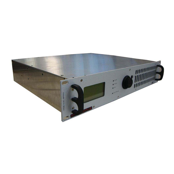
1.3 Location of parts. 1.3.1 Front panel description. The front panel of the EM 1000 HE DIG PLUS COMPACT is shown in the next picture: Figure 1.1: EM 1000 HE DIG PLUS COMPACT Front Panel The elements shown in the previous figure are described next: 1. - Page 19 EM 1000 HE DIG PLUS COMPACT 1.3.2 Rear panel description. The rear panel of the EM 1000 HE DIG PLUS COMPACT is shown in the next picture Figure 1.2: EM 1000 HE DIG PLUS COMPACT Rear Panel The elements shown in the previous figure are described next: 1.
-
Page 20: Installation
Should doubts or technical problems arise during the installation procedure, it is strongly recommended that you contact OMB or a local agent/dealer. • Should technical problems or doubts of any kind arise during installation, OMB would be happy to provide qualified technical assistance. Technical intervention by personnel not authorized by OMB should not be performed. - Page 21 FM TRANSMITTER EM 1000 HE DIG PLUS COMPACT • Room size should be such that the device can be placed in an upright position, and that technical personnel can easily perform routine or extraordinary maintenance. Evaluate the minimum size according to the power supplied by your model, taking into account that a volume of 2.5x2.2m in height is required for a transmitter with 1 KW of power, and that no...
- Page 22 FM TRANSMITTER EM 1000 HE DIG PLUS COMPACT • The power supply nominal range comes from 100-265VAC (nominal voltage single-phase 230VAC). • Mains fluctuations and electrical discharges due to weather or nearby industrial machinery may cause significant trouble, especially in mountain areas and in locations close to industrial areas.
- Page 23 FM TRANSMITTER EM 1000 HE DIG PLUS COMPACT 3) According to your model, connect the power cable or the device’s cable to a suitable single- phase input (230VAC nominal voltage). Before connecting the power, ensure that it is appropriate and is able to support the consumption required by the transmitter model you intend to use.
- Page 24 FM TRANSMITTER EM 1000 HE DIG PLUS COMPACT the PC port and a male DB9 connector to the transmitter. The applicable communication software is also required. - Never connect the cable if the PC or the transmitter are turned on.
-
Page 25: Table Of Contents
FM TRANSMITTER EM 1000 HE DIG PLUS COMPACT CONTENTS: 2.1 Audio Operation Modes ... . . 21 2.2 Basic Operations ....25 2.3 Menu and Navigation Commands . -
Page 26: Audio Operation Modes
FM TRANSMITTER EM 1000 HE DIG PLUS COMPACT 2.1 Audio Operation Modes. This section describes how to select the various available operating modes, and how to make audio connections according to your requirements. The transmitter is equipped with numerous characteristics specific to high-fidelity systems; as such, it should be connected to modulating signals with the same care as a Hi-Fi system, avoiding ground loops as much as possible. - Page 27 (RG62) cable should be used. 2.1.4 Connection to LEFT, RIGHT, or MPX modulation connectors The EM 1000 HE DIG PLUS COMPACT supports both balanced and unbalanced audio signals according to the connection that is made in the three LEFT and RIGHT XLR connector contacts.
- Page 28 FM TRANSMITTER EM 1000 HE DIG PLUS COMPACT 2.1.5 Connection to the MPX input Connect an externally created multiplex signal to the MPX input using a suitable encoder. If the length of the cable delivering the signal to the MPX connector is only a few meters long, a 50 Ohm (RG58) cable can be used.
- Page 29 FM TRANSMITTER EM 1000 HE DIG PLUS COMPACT 5) The input impedance is easily set using the JP1 e JP2 jumpers found on the input card, immediately after the input connectors as illustrated in the design. The selectable impedance values are serigraphed on the printed circuit board.
-
Page 30: Basic Operations
You can connect a suitable dummy load to the transmitter’s RF output instead of the antenna. 2) Turn on the device via the rear power switch. For a few seconds, the OMB logo will appear on the full screen; after this, the default screen will be displayed; the bottom of the default screen will show the two main menus, VIEW and SETUP. - Page 31 FM TRANSMITTER EM 1000 HE DIG PLUS COMPACT 2.2.2 Operating frequency 5) Ensure that the FREQUENCY sub-menu is selected; otherwise, turn the knob to select it. 6) Press the knob to access the sub-menu. The following screen will appear: 7) Ensure that the EDIT option is selected; otherwise, turn the knob to select it, then press to confirm.
- Page 32 FM TRANSMITTER EM 1000 HE DIG PLUS COMPACT 2.2.3 RF output power 13) Turn the knob until the POWER sub-menu is selected, then press to confirm. The power adjustment screen will appear: 14) Ensure that the EDIT option is selected; otherwise, turn the knob to select it, then press to confirm.
- Page 33 FM TRANSMITTER EM 1000 HE DIG PLUS COMPACT 21) Ensure that the EDIT option is selected; otherwise, turn the knob to select it, then press to confirm. 22) A value will be indicated after Nom. Input, normally pre-defined at +0.0dBm.
- Page 34 FM TRANSMITTER EM 1000 HE DIG PLUS COMPACT 29) Ensure that the EDIT option is selected; otherwise, turn the knob to select it, then press to confirm. 30) A value will be indicated after Limiter. This indicator is normally followed by OFF or by the limiter intervention value, expressed in dB, in reference to a deviation of 75 KHz.
- Page 35 FM TRANSMITTER EM 1000 HE DIG PLUS COMPACT 39) A value will be indicated after Pre-emphasis. Turn the knob until the pre-emphasis value for your geographical region is selected (50 microseconds in Spain), then press the knob to confirm the value.
- Page 36 FM TRANSMITTER EM 1000 HE DIG PLUS COMPACT 45) Ensure that the EDIT option is selected; otherwise, turn the knob to select it, then press to confirm. 46) The hour will be indicated after Time. Turn the knob and adjust the current hour, then press the knob to confirm.
- Page 37 FM TRANSMITTER EM 1000 HE DIG PLUS COMPACT 54) Turn the knob to select the main VIEW menu, then press to confirm. 55) The first page composing the VIEW menu will appear: 56) Verify that all parameters are correct, in particular: - Direct and reflected power, via the STATUS sub-menu.
- Page 38 FM TRANSMITTER EM 1000 HE DIG PLUS COMPACT 2.2.10 Changing from full operation to stand-by and vice-versa During normal operation, you can place the transmitter in stand-by by pressing the ON/STAND-BY button. The device is on stand-by when the ON LED changes from green to yellow.
-
Page 39: Menu And Navigation Commands
FM TRANSMITTER EM 1000 HE DIG PLUS COMPACT 2.3 Menu and Navigation Commands. To view the device’s operating parameters, and to set parameters according to your requirements, you will need to navigate the commands menu shown on the LCD display. You can navigate the menu using: •... - Page 40 FM TRANSMITTER EM 1000 HE DIG PLUS COMPACT You can also turn the knob clockwise and anti-clockwise to select the various screens showing data that can be viewed within a menu. For example, alarm events in the view alarms menu.
- Page 41 FM TRANSMITTER EM 1000 HE DIG PLUS COMPACT 5) Where required, use the knob according to the instructions provided in each of the following descriptions of the individual sub-menus. 6) To go back to the previous level (and exit the current menu/sub-menu), press the ESCAPE button.
-
Page 42: Description Of The Menu
FM TRANSMITTER EM 1000 HE DIG PLUS COMPACT 2.4 Description of the menu. 2.4.1 Default screen As soon as the device is turned on, the default screen will appear on the display, indicating the following information: • Model: indicates the transmitter model. - Page 43 FM TRANSMITTER EM 1000 HE DIG PLUS COMPACT VIEW Page 2 • STATUS – indicates the primary measurements, such as direct power, reflected power, etc. • L/R – for measuring modulation. • AUX – for measuring modulation of the auxiliary RDS/SCA signal.
- Page 44 FM TRANSMITTER EM 1000 HE DIG PLUS COMPACT function of the modulating signal, the modulation sensitivity must be set via the MPX SENS submenu, from the main SETUP menu. In addition, the bar indicator graphically shows the last parameter indicated.
- Page 45 FM TRANSMITTER EM 1000 HE DIG PLUS COMPACT The above example shows the standard level of the RDS signal (0KHz), as well as the bar indicator, which shows the level graphically. Adjustments can be made to modulation of the auxiliary signal via the SETUP menu.
- Page 46 FM TRANSMITTER EM 1000 HE DIG PLUS COMPACT • Frequency: indicates the operating frequency (in the example, 108.00MHz). • Mode: indicates Mono, Stereo, Mono L+R, or Mpx mode (in the example, Mpx). • Preemphasis: indicates the modulation preemphasis value (in the example, 50 microseconds).
- Page 47 FM TRANSMITTER EM 1000 HE DIG PLUS COMPACT The screen for this sub-menu indicates the current operating temperatures as follows: • CPU temp. – indicates the current CPU temperature (in the example, +27°C) • RF temp. – indicates the RF temperature, if pertinent to the model in use (in the example, +35°C)
- Page 48 FM TRANSMITTER EM 1000 HE DIG PLUS COMPACT If the device already has 100 events/alarms in its memory, a new event/alarm that occurs will cancel out the oldest recording so that the new event/alarm can be saved (FIFO). Via the SETUP menu, you can decide whether to activate/deactivate each alarm (e.g., low power, insufficient modulation, etc.), and set new detection thresholds.
- Page 49 FM TRANSMITTER EM 1000 HE DIG PLUS COMPACT SETUP Page 2 SETUP Page 3 To move from one page to another, select the commands NEXT PAGE or PREV PAGE using the knob, then press to confirm. As you can see, the three pages allow you to access the following settings: •...
- Page 50 FM TRANSMITTER EM 1000 HE DIG PLUS COMPACT - FREQUENCY setting It is used to define the transmitter’s operating frequency. The following parameters can be set: • Step – frequency increments can be selected (in the example, 100 KHz) • Frequency – operating frequency - POWER setting It is used to adjust the transmitter’s output power.
- Page 51 FM TRANSMITTER EM 1000 HE DIG PLUS COMPACT The display shows the following: • Mpx – followed by the deviation value, expressed in KHz (in the example, 0.0KHz) and in dB, in reference to a deviation of 75KHz (0dB = 75KHz) •...
- Page 52 FM TRANSMITTER EM 1000 HE DIG PLUS COMPACT of the deviation, the value of the modulating signal will be indicated in dB, against the nominal value set. 4) Ensure that the deviation measured does not exceed local regulations, then press the knob to confirm the setting.
- Page 53 FM TRANSMITTER EM 1000 HE DIG PLUS COMPACT The display shows the following: • Mode – followed by Mono (from the RIGHT input, Stereo, Mono L+R (monophony obtained through the sum of the stereo channels), or Mpx (external multiplex modulation signal originating from the MPX input.
- Page 54 FM TRANSMITTER EM 1000 HE DIG PLUS COMPACT • Contrast – followed by the current contrast value To change these parameters: 1) Ensure that the EDIT option is selected; otherwise, turn the knob to select it, then press to confirm. A value will be indicated after Backlight.
- Page 55 FM TRANSMITTER EM 1000 HE DIG PLUS COMPACT 3) Turn the knob to change the setting to LOW or HIGH according to your requirements, then press the knob to set the value. 4) Using the knob, select OK to save the settings, EDIT to make further changes, or ABORT to...
- Page 56 FM TRANSMITTER EM 1000 HE DIG PLUS COMPACT Used to set the date and time used by the system to generate an alarm history, and for other functions. The display shows the following: • Time – followed by the currently set time •...
- Page 57 FM TRANSMITTER EM 1000 HE DIG PLUS COMPACT • SET PASSWORD LEV 1 • SET PASSWORD LEV 2 • In order to gain confidence with the password settings menu and with its operation, we recommend that the password be set as 0 0 0 0 (four zeros) the first time.
- Page 58 FM TRANSMITTER EM 1000 HE DIG PLUS COMPACT LEVEL 2 PASSWORD If you wish to protect the SETUP menu only, activate/set the LEV 2 password using the same procedure as outlined above, ensuring that SET PASSWORD LEV 2 is selected at step 1).
- Page 59 FM TRANSMITTER EM 1000 HE DIG PLUS COMPACT 2) Ensure that the EDIT option is selected; otherwise, turn the knob to select it, then press to confirm. The first value to be set will be highlighted. 3) Turn the knob to change the setting according to your requirements, then press to set.
- Page 60 FM TRANSMITTER EM 1000 HE DIG PLUS COMPACT In the above example, the Refl. Power alarm is issued when a reflected power of 85.0 W is exceeded. To set the high reflected power alarm: 1) Ensure that the EDIT option is selected; otherwise, turn the knob to select it, then press to confirm.
- Page 61 FM TRANSMITTER EM 1000 HE DIG PLUS COMPACT 3) Using the knob, select OK to save the settings, EDIT to make further changes, or ABORT to exit without saving the new settings, then press to confirm - MPX From this screen, you can personalize the insufficient modulation alarm. Two parameters can be set: •...
- Page 62 FM TRANSMITTER EM 1000 HE DIG PLUS COMPACT When you access this menu, two simple commands are available by turning the knob: • YES – the alarm history will be deleted. The message waiting… will appear while the history is being deleted.
- Page 63 FM TRANSMITTER EM 1000 HE DIG PLUS COMPACT To set automatic power reduction: 1) Ensure that the EDIT option is selected; otherwise, turn the knob to select it, then press to confirm. A value will be displayed after OFF or ON.
- Page 64 IMPORTANT! Always note down the level 3 password and sore it in a safety place. Should you loose it, the total reprogramming of the equipment or the CPU replacement at OMB will be mandatory – with the related costs which this operation involves. This kind of service is not included in the warranty.
-
Page 65: Troubleshooting
EM 1000 HE DIG PLUS COMPACT 2.5 Troubleshooting. All instructions set in this manual are followed, the EM 1000 HE DIG PLUS COMPACT series will guarantee several years of perfect service. However, should problems arise, refer to this chapter before contacting the local authorized assistance point. - Page 66 FM TRANSMITTER EM 1000 HE DIG PLUS COMPACT - Unlock (unlocked PLL synthesizer) Unlock shows an unlock status of the built in synthesizer, generally meaning a real transmitter fault. When this failure happens it’s quite important to contact the local authorized assistance point.
- Page 67 FM TRANSMITTER EM 1000 HE DIG PLUS COMPACT CONTENTS: 3.1 Internal modules location......3.2 FM synthesizer....... . .
-
Page 68: Internal Modules Location
EM 1000 HE DIG PLUS COMPACT 3.1 Internal Modules Location. Next picture shows an internal view of the EM 1000 HE DIG PLUS COMPACT transmitter: Figure 3.1: EM 1000 HE DIG PLUS COMPACT Internal View The elements numbered in the previous picture are described next: 1. -
Page 69: Fm Synthesizer
FM TRANSMITTER EM 1000 HE DIG PLUS COMPACT 3.2 FM SYNTHESIZER This unit includes a classical phase-locked-loop circuit with 10 kHz-step synthesis across the entire FM band. The very low-noise, fundamental-frequency VCO (Voltage-Controlled Oscillator) consists of a FET oscillator transistor TR5, modulated by the varactor diode set D4~D7, which also sets the operating frequency. -
Page 70: Main Board
FM TRANSMITTER EM 1000 HE DIG PLUS COMPACT 3.3 MAIN BOARD Through this board the input audio signals, their level adjustment, filtering and limitation are processed; it also controls the level of RF power in the load or to the antenna; and contains the coupling interface for external supervision, control and monitoring. - Page 71 FM TRANSMITTER EM 1000 HE DIG PLUS COMPACT preset by the resistive network R49/R50. The third and fourth section of the integrated IC4 are used to filter and isolate the signal from the Microcontroller and which sets the reference threshold level for the RF output power control loop.
-
Page 72: Control Unit Board
FM TRANSMITTER EM 1000 HE DIG PLUS COMPACT 3.4 CONTROL UNIT BOARD The control unit board centers its mission on the processor, which is in charge of all the functions related to the equipment. The signals generated and adapted on the MAIN BOARD arrive on the board;... -
Page 73: Aux. Power Supply
EM 1000 HE DIG PLUS COMPACT 3.5 Auxiliary Power Supply The EM 1000 HE DIG PLUS COMPACT uses an AC/DC power supply, to provide auxiliary voltage to the different parts that make up the device. Figure: RD 3513 Power Supply... -
Page 74: Knob Encoder Board
FM TRANSMITTER EM 1000 HE DIG PLUS COMPACT 3.6 KNOB ENCODER BOARD Figure: Knob encoder board This board is sends the signals that come from the control unit to the DISPLAY. It also represents the external interface unit through a rotary encoder with pulsation. This encoder allows managing all the functions of the transmitter by accessing the menus and sub- menus. -
Page 75: Compada Board
FM TRANSMITTER EM 1000 HE DIG PLUS COMPACT 3.7 COMPADA BOARD This board has the following functions: x Connects the +/-12V power supply to modulator. x Controls power supply level voltage of the RF power stage. x It helps to improve the device’s efficiency in the whole working power range, reducing the supply voltage at the same time the output power reduces. - Page 76 FM TRANSMITTER EM 1000 HE DIG PLUS COMPACT COMPADA 1v1 BOARD DESCRIPTION REFERENCE QUANTITY Capacitor SMD 1206 ±10% 50V 100nF C1, C2, C3, C4, C5, C6, C9, C11, C12 Capacitor SMD 1206 1uF X7R>16V <± 10% C7, C8, C10 Capacitor SMD 1206 ±10% 16V 10uF Diode Schottky SOD323F 0.5A...
-
Page 77: Driver Module
FM TRANSMITTER EM 1000 HE DIG PLUS COMPACT 3.8 10W DRIVER BOARD Figure: 10W driver board This amplifier board receives the signal from the FM SYNTHETIZER module. The RF signal that comes from this module is filtered and amplified by a MOSFET Q1 MRF6V2010NBR5. The amplifier circuit has a variable power supply that ranges between 30Vdc and 50Vdc, after passing through the LM317 regulator, 30Vdds are obtained. -
Page 78: Main Power Supply And Low Pass Filter
FM TRANSMITTER EM 1000 HE DIG PLUS COMPACT 3.9 Main Power Supply The EM 1000 HE DIG PLUS COMPACT uses an AC/DC switching supply which work in parallel for powering the elements composing the amplifier. Figure: 2KW switching power supply... - Page 79 FM TRANSMITTER EM 1000 HE DIG PLUS COMPACT 3.9.1 Low Pass Filter The low pass filter attenuates the harmonics outside band II, at -70dbc levels, being placed in the drainage circuit of the output transistors. A directional coupler is also included in this section. It provides forward and reflected proportional Vdc voltages depending forward and reflected power.
-
Page 80: Power Amplifier 1200W
FM TRANSMITTER EM 1000 HE DIG PLUS COMPACT Low Pass Filter DESCRIPTION REFERENCE QUANTITY PCB filter 1v0 PCB 7.5pF PCB C1 PCB 11.7pF PCB C2 SMD Capacitor 1206 1nF C6, C7, C8, C9, C14,C15 SMD Capacitor 1206 10pF C10, C12... - Page 81 FM TRANSMITTER EM 1000 HE DIG PLUS COMPACT 3.10 1200W FM AMPLIFIER MODULE The amplifier module has been developed using a capsule with two MOSFET designed for its class B push pull operation. This module is able to deliver an output power of 1200W. It is powered by a voltage of +48V delivered by the switching power supplies of the equipment.
- Page 82 FM TRANSMITTER EM 1000 HE DIG PLUS COMPACT 1200W FM Amplifier Module DESCRIPTION REFERENCE QUANTITY SMD 0805 ±10% 50V 1nF Capacitor C1, C21, C28, C36 C2, C23, C29, C34, SMD 0805 ±10% 50V 100nF Capacitor SMD 1206 ±10% 50V 1uF Capacitor C3, C22, C35 SMD 1210 ±10% 200V 1nF Capacitor...
-
Page 83: Options
FM TRANSMITTER EM 1000 HE DIG PLUS COMPACT 3.11.1 STEREO GENERATOR BOARD (OPTIONAL) The phase control loop (PLL) circuit is contained entirely in the integrated circuit IC2, whose reference frequency is generated in a TCXO called TCXO1 in the diagram. The signal generated by this oscillator has a frequency of 12.8MHz. - Page 84 FM TRANSMITTER EM 1000 HE DIG PLUS COMPACT 3.11.2 RDS BOARD (OPTIONAL) The RDS generator is an advanced model that allows the transmission of all the most common standard services referred to in EN50067, EN62106 and EBU Tech.3244, and it is compatible with the UECP remote control protocol.
- Page 85 This optional interface board allows the remote control of transmitters and systems (of any type) manufactured by OMB via LAN or Internet, in particular the EM DIG PLUS series. In order to allow control of the system on which the board is installed, an IP address compatible with the user's LAN must be specified and accessible on the transmitter.
- Page 86 FM TRANSMITTER EM 1000 HE DIG PLUS COMPACT Ethernet BOARD, connector LAN: the flashing green LED indicates that the board is powered and functioning. The flashing speed increases when the software is updated. DATA: the flashing green LED indicates normal communication with the CPU system.
- Page 87 FM TRANSMITTER EM 1000 HE DIG PLUS COMPACT 3.11.4 AES/EBU INPUT (OPTIONAL) As defined by the Audio Engineering Society and the European Broadcast Union, this is the standard universally used on professional and broadcast equipment. The signal is carried on a balanced twisted shielded cable with 110 ohm impedance.
- Page 88 FM TRANSMITTER EM 1000 HE DIG PLUS COMPACT R&TTE DIRECTIVE 1999/5/CE Declaration of Conformity This equipment is in compliance with the essential English: requirements and other relevant provisions of Directive 1999/5/EC Dieses Gerät entspricht den grundlegenden Anforderungen und Deutsch: den weiteren entsprechenden Vorgaben der Richtlinie 1999/5/EU.
- Page 89 OMB SISTEMAS ELECTRÓNICOS S.A. OMB AMERICA C/ Paraguay nº 6 (Polígono Centrovía) 3100 NW 72nd. Ave. Unit 112 50198 La Muela (Zaragoza) – ESPAÑA MIAMI, Florida 33122 USA Tlf: +34 976 14 17 17 Tlf: (305) 477 0973 http://www.omb.com http://www.omb.com e mail: europa@omb.com...
- Page 90 FM TRANSMITTER EM 1000 HE DIG PLUS COMPACT Legal Notice: According to the European directives, 2002/96/CE and 2003/108/CE, it is forbidden to trash Waste Electrical and Electronic Equipment (WEEE) products along with normal wastes. The equipment classified cannot be disposed as urban waste but it must be sent to the specific collecting centres prepared by the municipal government and they will arrange the separate collection of WEEE.
- Page 91 FM TRANSMITTER EM 1000 HE DIG PLUS COMPACT INTENTIONALLY BLANK Technical Manual 1v2 November 2019...
Need help?
Do you have a question about the EM 1000 HE DIG PLUS COMPACT and is the answer not in the manual?
Questions and answers