Table of Contents
Advertisement
SISTEMAS ELECTRONICOS S.A.
C
O
C
O
OMB EUROPE:
Factory: Camino de los Albares,14 -Ph. 976.50.35.80, Fax: 976.50.38.55 – 50410 CUARTE DE HUERVA (Zaragoza) ESPAÑA
Sales
Dpt.: Avda. San Antonio,41– Ph. 976.50.46.96, Fax: 976.46.31.70 – 50410 CUARTE DE HUERVA (Zaragoza) ESPAÑA
E-mail:
europa@omb.com
Web:
www.omb.es
OMB USA:
3100 NW 72nd. Avenue Unit 112 – MIAMI, Florida 33122 – Ph.: 305 477-0973, 305 477-0974, Fax: 305 477-0611
E-mail:
usa@omb.com
www.omb.com
Web:
2
5
0
W
S
O
2
5
0
W
S
O
F
M
T
R
A
N
F
M
T
R
A
N
E
M
E
M
M
P
A
M
P
A
TECHNICAL MANUAL
v1.1 February 2006
L
I
D
S
T
A
T
E
L
I
D
S
T
A
T
E
S
M
I
T
T
E
R
S
M
I
T
T
E
R
2
5
0
2
5
0
C
T
D
C
T
D
I
G
I
G
Advertisement
Chapters
Table of Contents

Related Manuals for OMB EM 250 COMPACT DIG


Summary of Contents for OMB EM 250 COMPACT DIG
- Page 1 TECHNICAL MANUAL v1.1 February 2006 SISTEMAS ELECTRONICOS S.A. OMB EUROPE: Factory: Camino de los Albares,14 -Ph. 976.50.35.80, Fax: 976.50.38.55 – 50410 CUARTE DE HUERVA (Zaragoza) ESPAÑA Sales Dpt.: Avda. San Antonio,41– Ph. 976.50.46.96, Fax: 976.46.31.70 – 50410 CUARTE DE HUERVA (Zaragoza) ESPAÑA E-mail: europa@omb.com...
- Page 2 SISTEMAS ELECTRÓNICOS OMB ESPAÑA Av. San Antonio, 41 50410 Cuarte de Huerva ZARAGOZA (ESPAÑA) Website: http://www.omb.com e-mail: europa@omb.com Tlf: + 34 976 50 46 96 Fax: + 34 976 46 31 70 Nº Es01-022 Nº Es01-E021...
- Page 3 LIMITED WARRANTY _____________________________________________________________ About Installation 1. - Mains Voltage must be kept between ±10% about its nominal value, unless otherwise specified. If were variations exceeding this tolerance, it will be indispensable to install a voltage stabilizer system within station. If transient overvoltages, due to electric motors, or other devices of this sort connected to the distribution line, were present, or if the distribution line is exposed to atmospheric electrical discharges, it must be indispensable the installation of isolation transformers and gaseous dischargers before connecting any equipment within station.
- Page 4 checks, both for equipments and station itself, including air filters cleaning, measuring of transmission frequency with eventual correction if necessary, and will perform a general check of fundamental parameters of equipments. In the event of any important change in some operation parameter, that will require replacement or readjustment of any unit, Customer MUST CONTACT FIRST WITH O.M.B.
- Page 5 Customer. Otherwise, this Warranty will be automatically voided. This Warranty is self-activated with the reception by OMB Sistemas Electrónicos, S.A. of the "Guarantee Activation Manual" returned to OMB by Customer. If such Document is not received, this Warranty will be voided.
-
Page 6: List Of Contents
FM Transmitter Sistemas Electrónicos S.A EM 250 COMPACT DIG LIST OF CONTENTS SECTION 0. GENERAL RECOMMENDATIONS Gives information on safety procedures and good practices to use the equipment SECTION 1. GENERAL DESCRIPTION Introduction to the manual, technical specifications and description of the equipment’s features SECTION 2. - Page 7 FM Transmitter Sistemas Electrónicos S.A EM 250 COMPACT DIG Technical Manual - v1.1 - February 2006...
- Page 8 FM Transmitter Sistemas Electrónicos S.A EM 250 COMPACT DIG GENERAL SAFETY RECOMMENDATIONS When connecting the equipment to the Mains power, please follow these important recommendations: This product is intended to operate from a power source that will not apply more than 10% of the voltage specified on the rear panel between the supply conductors or between either supply conductor and ground.
- Page 9 FM Transmitter Sistemas Electrónicos S.A EM 250 COMPACT DIG FIRST AID IN CASE OF ELECTRICAL SHOCK If someone seems unable to free himself while receiving an electric shock, turn power off before rendering aid. A muscular spasm or unconsciousness can make a victim unable to free himself from the electrical power.
- Page 10 FM Transmitter Sistemas Electrónicos S.A EM 250 COMPACT DIG Step 5 Position your hands in the center of the chest between the nipples. Place one hand on top of the other. Step 6 Push down firmly two inches. Push on chest 15 times.
-
Page 11: Table Of Contents
FM Transmitter Sistemas Electrónicos S.A EM 250 COMPACT DIG CONTENTS : 1.1 Introduction ....1.2 Description ....7 1.3 Front panel . -
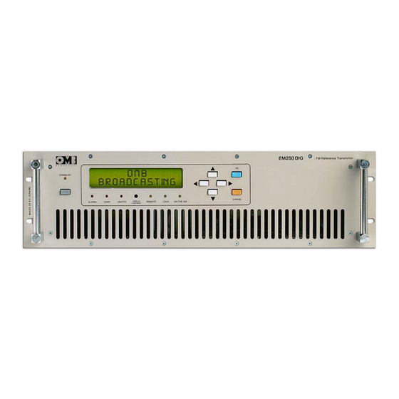
Page 12: Introduction
EM 250 COMPACT DIG 1.1 Introduction. The OMB EM-250 COMPACT DIG series transmitters are the result of experience gained by OMB during years of producing FM broadcast equipment, transmitters, stl and stereo encoders. These transmitters were specifically designed to comply with the latest international standards and the requirements of advanced broadcasters,meeting tighter specifications than usually required,at an affordable cost. - Page 13 FM Transmitter Sistemas Electrónicos S.A EM 250 COMPACT DIG Fig. 1-1: THE EM-250 COMPACT DIG DIGITALLY-CONTROLLED F.M. TRANSMITTER As imposed by various national standards, these transmitters incorporate sophisticated low-pass audio filters on mono and stereo channels,and a sharp acting modulation limiter, which is usually set at a peak deviation slightly higher than 75kHz.
-
Page 14: Front Panel
FM Transmitter Sistemas Electrónicos S.A EM 250 COMPACT DIG 1.3 Front panel. The EM-250 COMPACT DIG Front Panel is very clean and easy to control.The wide alphanumeric display and the control keyboard allows a simple self-explanatory menu-driven navigation through the various options. - Page 15 FM Transmitter Sistemas Electrónicos S.A EM 250 COMPACT DIG • On the air green LED works together with STANDBY (2) yellow LED. It lights on when equipment is in normal operating condition, whereas STANDBY (2) LED is turned off, and vice versa.
-
Page 16: Rear Panel
DB-9 or DB-25 female to the PC port and a male DB9 connector at the transmitter end. Appropriate OMB software is required for communication. Do not connect the serial cable with neither transmitter or PC turned - RF sample output for frequency measuring or RF signal monitoring, BNC female type connector. -
Page 17: Inner Layout
FM Transmitter Sistemas Electrónicos S.A EM 250 COMPACT DIG 1.5 Inner layout. Figure 1-4 below shows space occupied and allocation of the different units and PC boards within equipment, and internal arrangement of cabinet. All boards and units can be easily and quickly... -
Page 18: Technical Specifications
FM Transmitter Sistemas Electrónicos S.A EM 250 COMPACT DIG 1.6 Technical specifications. SIGNAL TO NOISE RATIO Monaural >78dB, typical 86dB (from 30 to 20,000Hz) Stereophonic >72dB, typical 77dB (from 30 to 20,000Hz) CCIR WEIGHTED S/N Monaural >75dB, typical 81dB. Stereophonic >68dB, typical 77dB. -
Page 19: Technical Manual - V1.1 - February
FM Transmitter Sistemas Electrónicos S.A EM 250 COMPACT DIG CONTENTS : 2.1 Introduction ....15 2.2 Audio processor and R.F. control main board . 19 2.3 Stereo encoder (optional) . -
Page 20: Introduction
FM Transmitter Sistemas Electrónicos S.A EM 250 COMPACT DIG 2.1 Introduction. The EM-250 COMPACT DIG transmitter comprises 5 or 6 internal modules, as can be seen in the general upper view (Figure 1-4) and in the General Wiring Diagram (in next pages). Main units are the following: The Main Audio Processor Board. - Page 21 Date Name Signature: OMB Eng. Dpt. Drawn Checked Standards Sistemas Electrónicos S.A. Scale: EM 250 COMPACT DIG Ttle: Drawing nr: General cabinet layout Replace: Replaced with:...
- Page 22 Date Name Signature: OMB Eng. Dpt. Drawn Checked Standards Sistemas Electrónicos S.A. Scale: EM 250 COMPACT DIG Ttle: Drawing nr: : Inner layout Replace: Replaced with:...
-
Page 24: Audio Processor And R.f. Control Main Board
FM Transmitter Sistemas Electrónicos S.A EM 250 COMPACT DIG 2.2 Audio processor and R.F. control main board. This is the most complex board in the transmitter and supports the Audio input processing, its level adjustment, audio-pass filtering and limiting, the RF control section and the I/O interfaces. It also interconnects the various transmitter modules with ribbon-type cables. - Page 25 FM Transmitter Sistemas Electrónicos S.A EM 250 COMPACT DIG Let's now go to the second sheet of this diagram. Beginning from the lower left side,we find IC8, which makes a 3-channel digitally controlled attenuator. It separately manages left, right and auxiliary channel, while the externalmultiplex signal is processed in the same channel as the right one.
- Page 28 Date Signature: Name Drawn 01/11/04 OMB Eng. Dpt. Checked Standards Sistemas Electrónicos S.A. Scale: Title: EM 250 COMPACT DIG Drawing nr: Mainboard Replace: Replaced with:...
-
Page 29: Stereo Encoder (Optional)
FM Transmitter Sistemas Electrónicos S.A EM 250 COMPACT DIG 2.3 Stereo encoder (optional). The encoding circuit uses an 8-step switching technique,which ensures excellent performance with a relatively simple circuit. In addition, by this technique, the first harmonics that are associated with the... - Page 31 Date Name Signature: Drawn 01/11/04 OMB Eng. Dpt. Checked Standards Sistemas Electrónicos S.A. Scale: Title: EM 250 COMPACT DIG Drawing nr: Stereo encoder Replace: Replaced with:...
-
Page 32: Exciter Unit
FM Transmitter Sistemas Electrónicos S.A EM 250 COMPACT DIG 2.4 FM Exciter unit. This unit includes a classical phase-locked-loop circuit with 10kHz-step synthesis across the entire FM band. The very low-noise, fundamental-frequency VCO (Voltage-Controlled Oscillator) consists of a FEToscillator transistor TR5, modulated by the varactor diode set D4~D7, which also sets the operating frequency. - Page 34 Date Signature: Name Drawn 01/11/04 OMB Eng. Dpt. Checked Standards Sistemas Electrónicos S.A. Scale: Title: EM 250 COMPACT DIG Drawing nr: FM Exciter Replace: Replaced with:...
-
Page 35: Power Amplifier Module
FM Transmitter Sistemas Electrónicos S.A EM 250 COMPACT DIG 2.5 R.F. Power Amplifier module. This stage is designed with only one high gain BLF-278 MOSFET RF power transistor capsule, in a broadband class AB common emitter design, with +48V supply : Fig. - Page 36 FM Transmitter Sistemas Electrónicos S.A EM 250 COMPACT DIG Detailed views of the three sections composing the Power Amplifier module are shown in Figures 2-4, 2-5 and 2-6 below: Fig. 2-4: DETAILED VIEW OF INPUT DRIVER STAGE. Figure 2-4 above shows a magnified view of RF driver stage, a BLF 242 transistor working in class AB configuration.
- Page 37 FM Transmitter Sistemas Electrónicos S.A EM 250 COMPACT DIG Fig. 2-5: DETAIL OF OUTPUT AMPLIFIER SECTION. Elements numbered in Figure 2-5 can be described as follows: - Input splitter transformer and coupling circuit. - Bias adjustment potentiometer. - Bias regulator circuit.
- Page 38 The output transistors capsule is a rugged device which easily could pass the nominal 250W power output, even increasing this power output out of limits, to 300W. OMB suggests never exceeding 250 ~ 270W output power, even when the transmitter could generate more than this.
- Page 39 FM Transmitter Sistemas Electrónicos S.A EM 250 COMPACT DIG Driver FM v1.2.6 DESCRIPTION REFERENCE QUANTITY 100V 100nF Electrolytic cap SMD tantalum TAJ 35V 10uF SMD 200V RF 150pF SMD 200V RF 270pF SMD >=50V 68pF SMD 1206 100V 1nF C7-C8...
Need help?
Do you have a question about the EM 250 COMPACT DIG and is the answer not in the manual?
Questions and answers