Table of Contents
Advertisement
Quick Links
SISTEMAS ELECTRONICOS S.A.
B
R
O
A
B
R
O
A
E
E
OMB EUROPE:
Factory: Camino de los Albares,14 -Tlf. 976.50.35.80, Fax: 976.50.38.55 – 50410 CUARTE DE HUERVA (Zaragoza) ESPAÑA
Sales
Dpt.: Avda. San Antonio,41– Tlf. 976.50.46.96, Fax: 976.46.31.70 – 50410 CUARTE DE HUERVA (Zaragoza) ESPAÑA
E-mail:
europa@omb.com
Web:
www.omb.es
OMB USA:
3100 NW 72nd. Avenue Unit 112 – MIAMI, Florida 33122 – Ph.: 305 477-0973, 305 477-0974, Fax: 305 477-0611
usa@omb.com
E-mail:
Web:
www.omb.com
F
M
B
F
M
B
D
C
A
S
T
D
C
A
S
T
M
1
0
M
1
0
TECHNICAL MANUAL
v1.2 November 2005
A
N
D
I
I
A
N
D
I
I
T
R
A
N
S
T
R
A
N
S
0
D
I
0
D
I
M
I
T
T
E
R
M
I
T
T
E
R
G
G
Advertisement
Table of Contents

Related Manuals for OMB EM 100 DIG


Summary of Contents for OMB EM 100 DIG
- Page 1 TECHNICAL MANUAL v1.2 November 2005 SISTEMAS ELECTRONICOS S.A. OMB EUROPE: Factory: Camino de los Albares,14 -Tlf. 976.50.35.80, Fax: 976.50.38.55 – 50410 CUARTE DE HUERVA (Zaragoza) ESPAÑA Sales Dpt.: Avda. San Antonio,41– Tlf. 976.50.46.96, Fax: 976.46.31.70 – 50410 CUARTE DE HUERVA (Zaragoza) ESPAÑA E-mail: europa@omb.com...
- Page 2 LIMITED WARRANTY _____________________________________________________________ About Installation 1. - Mains Voltage must be kept between ±10% about its nominal value, unless otherwise specified. If were variations exceeding this tolerance, it will be indispensable to install a voltage stabilizer system within station. If transient overvoltages, due to electric motors, or other devices of this sort connected to the distribution line, were present, or if the distribution line is exposed to atmospheric electrical discharges, it must be indispensable the installation of isolation transformers and gaseous dischargers before connecting any equipment within station.
- Page 3 checks, both for equipments and station itself, including air filters cleaning, measuring of transmission frequency with eventual correction if necessary, and will perform a general check of fundamental parameters of equipments. In the event of any important change in some operation parameter, that will require replacement or readjustment of any unit, Customer MUST CONTACT FIRST WITH O.M.B.
- Page 4 Customer. Otherwise, this Warranty will be automatically voided. This Warranty is self-activated with the reception by OMB Sistemas Electrónicos, S.A. of the "Guarantee Activation Manual" returned to OMB by Customer. If such Document is not received, this Warranty will be voided.
-
Page 5: Technical Manual - V1.2 - November 2005
FM Transmitter Sistemas Electrónicos S.A EM 100 DIG LIST OF CONTENTS SECTION 0. GENERAL RECOMMENDATIONS Gives information on safety procedures and good practices to use the equipment SECTION 1. GENERAL DESCRIPTION Introduction to the manual, technical specifications and description of the equipment’s features SECTION 2. -
Page 6: Section 0. General Recommendations
FM Transmitter Sistemas Electrónicos S.A EM 100 DIG Technical Manual - v1.2 - November 2005... - Page 7 FM Transmitter Sistemas Electrónicos S.A EM 100 DIG GENERAL SAFETY RECOMMENDATIONS When connecting the equipment to the Mains power, please follow these important recommendations: This product is intended to operate from a power source that will not apply more than 10% of the voltage specified on the rear panel between the supply conductors or between either supply conductor and ground.
- Page 8 FM Transmitter Sistemas Electrónicos S.A EM 100 DIG FIRST AID IN CASE OF ELECTRICAL SHOCK If someone seems unable to free himself while receiving an electric shock, turn power off before rendering aid. A muscular spasm or unconsciousness can make a victim unable to free himself from the electrical power.
- Page 9 FM Transmitter Sistemas Electrónicos S.A EM 100 DIG Step 4 Put the fingertips of your hand on the Adam's apple, slide them into the groove next to the windpipe. Feel for a pulse. If you can not feel a pulse or are unsure, move on to the next step.
-
Page 10: Section 1. General Description
FM Transmitter Sistemas Electrónicos S.A EM 100 DIG CONTENTS : 1.1 Introduction ....7 1.2 General description ... . 7 1.3 Description of panels . -
Page 11: Introduction
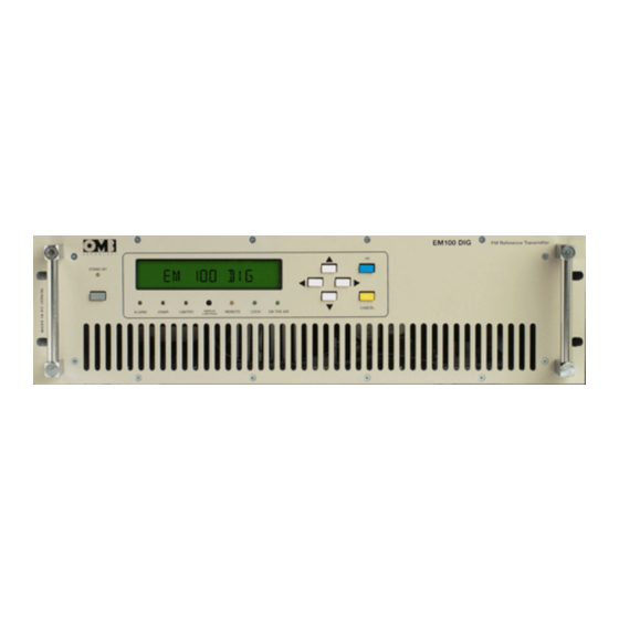
EM 100 DIG 1.1 Introduction. The OMB EM-100 DIG series transmitters are the result of experience adquired by OMB during years of producing FM broadcast equipment, transmitters, STL and stereo encoders. These transmitters were specifically designed to comply with the latest international standards and the requirements of advanced broadcasters, meeting tighter specifications than usually required,at an affordable cost. - Page 12 FM Transmitter Sistemas Electrónicos S.A EM 100 DIG Figure 1-1: EM-100 DIG DIGITALLY-CONTROLLED F.M. TRANSMITTER. As imposed by various national standards, these transmitters incorporate sophisticated low-pass audio filters on mono and stereo channels,and a sharp acting modulation limiter, which is usually set at a peak deviation slightly higher than 75kHz.
-
Page 13: Description Of Panels
FM Transmitter Sistemas Electrónicos S.A EM 100 DIG 1.3 Description of panels. The EM-100 DIG Front Panel is very clean and easy to control. The wide alphanumeric display and the control keyboard allows a simple self-explanatory menu-driven navigation through the various options. - Page 14 FM Transmitter Sistemas Electrónicos S.A EM 100 DIG - OPERATION LEDs PANEL: Remote amber LED shows remote-controlled operation is being carried on. Lock green LED shows when Channel Oscillator's PLL is properly locked,some tenths of second after equipment is turned on.
- Page 15 DB-9 or DB-25 to the PC port and a male DB-9 connector at the transmitter end. Appropriate OMB software is required for communication.
-
Page 16: Technical Specifications
FM Transmitter Sistemas Electrónicos S.A EM 100 DIG 1.4 Technical specifications. SIGNAL TO NOISE RATIO Monaural >78dB. typical 86dB from 30 to 20,000Hz. Stereophonic >72dB. typical 77dB from 30 to 20,000Hz. CCIR WEIGHTED S/N Monaural >75dB. typical 81dB Stereophonic >68dB. typical 77dB HARMONIC DISTORTION For ±... -
Page 17: Table Of Contents
FM Transmitter Sistemas Electrónicos S.A EM 100 DIG CONTENTS : 2.1 Introduction....14 2.2 System connection ....14 2.3 Audio Base band connections and presets. -
Page 18: Technical Manual - V1.2 - November
FM Transmitter Sistemas Electrónicos S.A EM 100 DIG 2.1 Introduction. Before proceeding further, make sure that mains voltage corresponds to the factory-set value (usually 220/240V ). In case it differs, change to the proper value. Install the transmitter in a dry, ventilated and possibly dust-free environment, so that it will operate in the +10 ~+35°C temperature range. -
Page 19: Audio Base Band Connections And Presets
FM Transmitter Sistemas Electrónicos S.A EM 100 DIG The first request it will do will be entering the password for the required level of authorization/security.The equipment is factory pre-set with the first 2 passwords levels disabled: this will allow to set most of the operating parameters, including power, frequency, input levels, clock and date. - Page 20 FM Transmitter Sistemas Electrónicos S.A EM 100 DIG connected to pin 3 (+) and pin 2 (-). The cable shield, connected to the ground of the driving equipment,has to be connected to pin 1. In case of unbalanced drive, input pin 2 shall be short-circuited with ground and shield on pin 1, while the signal shall be available on pin 3.
- Page 21 (headroom). It may also be costly to produce with high quality. For this reason OMB recommends,whenever possible,to adopt +6 ~ +11.5dBm as nominal peak level for audio modulation purposes.
- Page 22 DB-9 or DB-25 female to the PC port and a male DB-9 connector at the transmitter end. Appropriate software is needed for communication. OMB can provide this software and also Telemetry Equipment at request. Do not connect the cable with neither transmitter or PC energized.
-
Page 23: Operation
FM Transmitter Sistemas Electrónicos S.A EM 100 DIG 2.4 Operation 2.4.1 Monaural Broadcasting,from a Monophonic Audio Source through Main Monaural Channel. 1) Connect the “right ”(or mono) input connector to the corresponding audio source as described in the "system connection" section. No connection to the "left" channel input is needed. The signal runs through the channel processor and is 15kHz filtered and pre-emphasized. - Page 24 FM Transmitter Sistemas Electrónicos S.A EM 100 DIG 2.4.5 Operation with a RDS or SCA Encoder. 1) Connect the BNC-type <AUX> connector to the output of the RDS or SCA Encoder. If the internal optional stereo coder is used, connect the <LF MONITOR> BNC output to the pilot tone synchronization input of the RDS coder, if present.
-
Page 25: Commands And Programming
Its use is reserved only to service technicians who need wide access to the transmitter presets and functions. Although the default factory state is "off", OMB suggests changing the default state and password immediately at the first power on, to prevent to unauthorized people to tamper with transmitter commands, if the default word is known or the status is set to "off". -
Page 26: Factory Default Passwords
FM Transmitter Sistemas Electrónicos S.A EM 100 DIG WARNING Gaining again access to the equipment will require Factory reprogramming or changing the internal Control Unit . For practically any parameters that may require some setting in the field, the 2nd level password is enough and may be used for any standard service requirement. - Page 27 FM Transmitter Sistemas Electrónicos S.A EM 100 DIG Few minutes of tests will enable most users to gain confidence with control keys and menu and to be able to access to all main feature of the transmitter,without any previous training.
- Page 28 FM Transmitter Sistemas Electrónicos S.A EM 100 DIG Figure 2-1: SEQUENCE OF MENUS DISPLAYED BY SCREEN. HYERARCHICAL TREE. Technical Manual - v1.2 - November 2005...
- Page 29 FM Transmitter Sistemas Electrónicos S.A EM 100 DIG #00:D EFAULT ESSAGE OMB EM-100 DIG VER 1.0 This screen shows the default message and the software release.It is the field that will be initially set, or to which it will return back after repeated CANCEL commands.
- Page 30 FM Transmitter Sistemas Electrónicos S.A EM 100 DIG uncertainty. In this case the MPX level reading will anyway produce correct overall modulation measure. # 04:L &R IGHT IGNAL EVELS EEN AS NALOG OVING This screen shows the actual left and right peak modulation as two moving bars.A vertical line marks 0dB position and the same considerations as the previous menu are still valid.
- Page 31 FM Transmitter Sistemas Electrónicos S.A EM 100 DIG Entering in command mode, with the 2 level password authorization,permits to set every of this transmission parameters.See menu #27. Only 3 level authorization permits,pressing "Right" key, to change the frequency variation between 10 and 100kHz /step.
- Page 32 FM Transmitter Sistemas Electrónicos S.A EM 100 DIG If the code or the status is changed, it is always required to confirm the correct password for that level. If the password is unknown, lost or tamperers changed it, it is possible to change status and code when in possession of the higher password.
- Page 33 FM Transmitter Sistemas Electrónicos S.A EM 100 DIG This screen in command mode, with the 2 level password authorization, permits to set LF input channels sensitivity, i.e.multiplex, left and right channel. Take present that multiplex and left signals share the same channel and the sensitivity is set to the same value for both left (or multiplex)and right channel,with a differential error <0.2dB at any level.
- Page 34 FM Transmitter Sistemas Electrónicos S.A EM 100 DIG # 29:D ATA AND set data & time This screen is the command mode display of menu #09,with the 2 level password authorization and permits to set correct data and time. As in the last menu,the left and right keys change the input fields while the up and down keys increase/decrease the date and time.
-
Page 35: Service And Maintenance
After a few years of continuous service, it is recommended that the equipment be overhauled in the factory or in a OMB specialized laboratory. It is especially important that the Main Power Supply be overhauled when the Transmitter have been working at high temperatures, over 30 /35°C. -
Page 36: Section 3. Technical Information
FM Transmitter Sistemas Electrónicos S.A EM 100 DIG CONTENTS : 3.1 Introduction....33 3.2 Main board ....33 3.3 Stereo encoder (optional). -
Page 37: Main Board
FM Transmitter Sistemas Electrónicos S.A EM 100 DIG 3.1 Introduction. The EM-100 DIG transmitter comprises 5 or 6 internal modules. Main units are the following: Main Board. Microcontroller Unit & Display Board. Stereo Coder Module (optional) RF Exciter Board. RF Power Amplifier Module. - Page 38 FM Transmitter Sistemas Electrónicos S.A EM 100 DIG Figure 3-1: Main board. On the lower right section of the diagram it is located the RF power controller.The RF forward and reflected power signals coming from the output directional coupler (this located at RF Power Module) are amplified by IC3 in a symmetrical circuit.
- Page 41 Date Signature: Name Drawn 01/11/04 OMB Eng. Dpt. Checked Standards Sistemas Electrónicos S.A. Scale: Title: EM 100 DIG Drawing nr: Mainboard Replace: Replaced with:...
- Page 42 FM Transmitter Sistemas Electrónicos S.A EM 100 DIG 3.3 Stereo Encoder (optional). The encoding circuit uses an 8-step switching technique,which ensures excellent performance with a relatively simple circuit.In addition,by this technique,the first harmonics that are associated with the switching devices are the 7 and 9 (266 and 342kHz);...
- Page 44 Date Name Signature: Drawn 01/11/04 OMB Eng. Dpt. Checked Standards Sistemas Electrónicos S.A. Scale: Title: EM 100 DIG Drawing nr: Stereo encoder Replace: Replaced with:...
- Page 45 FM Transmitter Sistemas Electrónicos S.A EM 100 DIG 3.4 FM Exciter. This unit includes a classical phase-locked-loop circuit with 10kHz step synthesis across the entire FM band. The very low-noise, fundamental-frequency VCO (Voltage-Controlled Oscillator) consists of a FEToscillator transistor TR5, modulated by the varactor diode set D4~D7, which also sets the operating frequency.
- Page 47 Date Signature: Name Drawn 01/11/04 OMB Eng. Dpt. Checked Standards Sistemas Electrónicos S.A. Scale: Title: EM 100 DIG Drawing nr: FM Exciter Replace: Replaced with:...
- Page 48 FM Transmitter Sistemas Electrónicos S.A EM 100 DIG 3.5 R.F. Power Amplifier module. This stage is designed with only one high-gain BLF-278 MOSFET RF power transistor capsule, in a broadband class AB common emitter design. The elements contained in this module are: - Cooling fan directed towards heat sink's cooling fins.
- Page 49 FM Transmitter Sistemas Electrónicos S.A EM 100 DIG Elements numbered in Figure 3-3 can be described as follows: - Input splitter transformer and coupling circuit. - Bias adjustment potentiometer. - Bias regulator circuit. - MOSFET push-pull arranged, twin-transistor capsule. - Output combiner transformer and matching circuit.
- Page 50 The output transistors capsule is a rugged device which easily could pass the nominal 100W power output, even increasing this power output out of limits, to 300W. OMB suggests never exceeding 250 ~ 270W output power, even when the transmitter could generate more than this.
- Page 52 Date Signature: Name Drawn 04/05/04 M. Tsvelev Checked Standards Sistemas Electrónicos S.A. Scale: Title: MODPOT v1.3 Drawing nr: 300W R.F. Power Amplifier Replace: Replaced with:...
- Page 54 FM Transmitter Sistemas Electrónicos S.A EM 100 DIG 3.6 Control unit and display board. This circuit board is basically simple.It contains the Microcontroller,the keyboard and few other circuits which we will briefly discuss.Control & Display Units are shown in Figure 3-5 below. The Microcontroller has 3 digital 8-bit ports and an analog one.
- Page 55 FM Transmitter Sistemas Electrónicos S.A EM 100 DIG - ON THE AIR indicator LED. - External control keyboard. - CANCEL key, to suppress any order or command. - OK data entering key, to confirm any order or command. - Two-rows, backlighted alphanumeric LCD display.
- Page 57 Component side Solder side Date Signature: Name Drawn 18/04/03 OMB Eng. Dpt. Checked Standards Sistemas Electrónicos S.A. Scale: Title: EM 100 DIG Drawing nr: Control unit Replace: Replaced with:...
- Page 59 Date Signature: Name Drawn 16/07/02 OMB Eng. Dpt. Checked Standards Sistemas Electrónicos S.A. Scale: Title: EM 100 DIG Drawing nr: Keyboard / display interface Replace: Replaced with:...
-
Page 60: Power Supply
FM Transmitter Sistemas Electrónicos S.A EM 100 DIG 3.7 Power Supply. The main switching power supply is a sturdy unit , having a high-efficiency, S-240-30. A diode bridge full-wave rectifies the power transformer secondary voltage in the externally preset 88~132V 176~264V mains range transformer tap. - Page 61 FM Transmitter Sistemas Electrónicos S.A EM 100 DIG INTENTIONALLY BLANK Technical Manual - v1.2 - November 2005...
Need help?
Do you have a question about the EM 100 DIG and is the answer not in the manual?
Questions and answers