Lenz Digital plus LH100 Instructions Manual
Hide thumbs
Also See for Digital plus LH100:
- Information manual (16 pages) ,
- Information sheet (168 pages)

Related Manuals for Lenz Digital plus LH100


Summary of Contents for Lenz Digital plus LH100
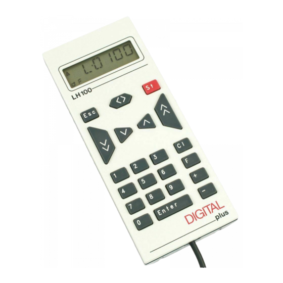
- Page 1 Information LH100 V3 Designed for use on all XpressNET systems LH100 Keypad based Dispatcher's Throttle Version 3.0 art. no. 21100 edition August 2000 Submitted to the NMRA for Conformance and Inspection testing DIGITAL plus...
- Page 2 Information LH100 V3 Welcome! ® Congratulations for purchasing the Digital plus by Lenz hand held controller LH100-V3. We wish you much enjoyment with using this model train control system. The LH100 hand held controller is the universal data input device ®...
-
Page 3: Important Information - Please Read First
® Digital plus by Lenz system and was subjected to intense testing before shipping. Lenz Elektronik GmbH guarantees problem free operation when you follow these directions: Depending on which command station (and which software version) you operate your LH100 on, certain functions are not or are only partially available. -
Page 4: Method For Describing Commands Within This Manual
All the described steps assume that the hand held controller connected Version ® system, and that this system is Digital plus by Lenz turned on. Showing displays and keys in text: "E 0001" 'Enter' In most cases the display of LH100 is showed as a picture, as are the keys. -
Page 5: Table Of Contents
Information LH100 V3 Contents Important information — Please read first!............3 Method for describing commands within this manual: ......... 4 Contents ......................5 First steps ......................7 Connections and starting operation..............7 Operating Your first Train ..................8 Overview of the functions of LH100 ..............11 Controlling locomotives .................. - Page 6 Information LH100 V3 Displaying feedback................... 41 Reading/Changing decoder settings ..............42 13.1 What is programming and what purpose does it serve? ........42 13.2 Programming on the Main - PoM ............... 45 13.3 Programming on the Programming track ............49 13.4 Error messages during programming ..............
-
Page 7: First Steps
3.1 Connections and starting operation The LH100 can be connected to any XpressNET system including ® the following components of the Digital plus by Lenz system: LZ100; SET02; SET03; Compact It may also be used with other XpressNET systems including the Atlas Commander and the Roco Lokmaus 2 system. -
Page 8: Operating Your First Train
Information LH100 V3 to addresses 1 through 31. Each hand held controller LH100 has its factory default address set to address 01. If you already have an LH100 at this address or operate another XpressNET device on this address, you must set your new LH100 to another address. Information on setting the XpressNET address can be found in the ð... - Page 9 Information LH100 V3 This key also increases the If you press this key and keep speed of the locomotive. If you it pressed, the speed of the press the key and keep it locomotive will automatically be pressed, the speed steps will decreased until speed step 0 is automatically increased...
- Page 10 Information LH100 V3 The '<>' key also has another function: It affects an emergency stop for the specific locomotive contained in the display. If the locomotive is operating at a speed step greater than 00, then pressing the '<>' key will lead to an emergency stop of this one locomotive.
-
Page 11: Overview Of The Functions Of Lh100
Information LH100 V3 Overview of the functions of LH100 This section will provide you: a short overview of each of the functions of LH100. Specific details for using each feature follows in subsequent subsections, which follow this section. 4.1 Controlling locomotives 4.1.1 Selecting locomotive addresses There are 3 different ways to select a locomotive address. -
Page 12: The Function Menu Of Lh100
Information LH100 V3 4.2 The function menu of LH100 The LH100 function menu provides you access to all other functions of the LH100. The different menu items can be reached in 2 different ways when you are in the locomotive control mode: Option 1: Press and scroll through... - Page 13 To allow control via the LH100, these devices must be connected accessory decoders LS100/110/120 ® system or other compatible modules. The Digital plus by Lenz procedure is controlling these devices using the LH100 is described in "Throwing turnouts and setting signals" starting on ð page ( p.38 ). 4.2.5...
- Page 14 Information LH100 V3 4.2.6 Configuring decoder settings: Programming Each decoder has settings that can be set to customize the decoder to an individual locomotive, for example the locomotive's address. The user-settable acceleration and deceleration delays are also configurable settings on a locomotive decoder. These settings can be changed by a technique we refer to as programming.
-
Page 15: The Lh100 Lcd Display
Information LH100 V3 The LH100 LCD Display In this section you will learn about the LH100 two-row LCD display. Depending on which mode of operation you are using, the display will look different. The display for the locomotive address always uses 4 digits. -
Page 16: Controlling Locomotives With The Lh100
Information LH100 V3 While the speed step is displayed, the locomotive address is hidden. The direction of travel and the functions continue to be displayed. Controlling locomotives with the LH100 In this section you will learn about basic locomotive control using the LH 100. -
Page 17: Quickly Toggling Between 2 Locomotive Addresses
Information LH100 V3 You continue by pressing each number in the locomotive's address After you have entered the complete locomotive address you confirm the entry by pressing the 'Enter' key. The information about functions, direction and speed step associated with this address will now be displayed. -
Page 18: Selecting An Address From The Command Station Stack
Information LH100 V3 key. From now on, you can use the ‘Esc’ key to toggle between address 24 and 78. If you press the ‘Cl’ key, then the locomotive address in the memory currently shown is erased; the locomotive address in the second memory is still available for use. 6.4 Selecting an address from the command station stack The command station stack is a database that contains all the... -
Page 19: Taking Over Control Of A Locomotive From Another Hand Held Controller
The functions are numbered, beginning with ® 0. Altogether the Digital plus by Lenz system can reach up to 13 functions in locomotive decoders. Functions 0-8 can be activated directly while you are controlling a locomotive (that is the locomotive address or the speed step is displayed), using keys the ‘0’... - Page 20 Information LH100 V3 Press On the display you see Explanation This function 0 is assigned to the headlights in most locomotive decoders and is shown by the lamp symbol in the lower row of the display. The state of functions 1 to 8 is shown in the second row next to the “F”.
-
Page 21: Showing And Changing Throttle-Notches
Information LH100 V3 6.7 Showing and changing throttle-notches In this section you learn: what throttle-notches are which throttle-notches are available to you how to select different throttle-notches individual locomotive addresses. The area from stopped to maximum speed of a locomotive is divided into a series of throttle-notches. - Page 22 CV29 decoder. details, ® "Information for locomotive decoders". Digital plus by Lenz You must make sure that the locomotive decoder also “understands” the programmed speed step mode. For Digital plus decoders the following correspondence applies: DIGITAL plus locomotive supported speed step...
-
Page 23: Emergency Stop And Emergency Off
Information LH100 V3 Emergency stop and emergency off In this section you will learn about: the function of the key. how to turn off track power changing information during an emergency stop The 'St' key tells the system to perform an emergency stop. You can program this key to have two different effects : Emergency stop Emergency off... -
Page 24: Changing Operating Information During Emergency Stop/Off
Information LH100 V3 You start the power off sequence by first pressing the 'F' key. Next you press the '0' key. The track power is now turned off (flashes) Pressing the ‘St’ key a second time resets the emergency stop, the track power is turned on again. -
Page 25: Switching Turnouts During Emergency Stop
Information LH100 V3 7.3 Switching turnouts during emergency stop Since the track power remains on during the emergency stop, you can continue to switch turnouts and signals: Press On the display you see Explanation The emergency stop or emergency off is displayed alternates with You return to controlling locomotives with 'Esc'. - Page 26 Information LH100 V3 the corresponding key is pressed. When you release the key, the function being controlled is turned off again. This setting is stored in the LZ100 command station. The LH100 hand held controller will check these settings each time a locomotive is called up.
-
Page 27: Double Header
Information LH100 V3 When you want to change the settings for functions 9 to 12, then proceed as follows: Press On the display you see Explanation Call up the locomotive address whose function setting you want to display or change. Go to setting the functions Pressing ‘9’... -
Page 28: Prerequisites For Creating A Double Header
Information LH100 V3 The LH100 allows you to assign two locomotives to operate together as a double header, and then control them as if they were a single locomotive. 9.1 Prerequisites for creating a double header You must have called up on the same hand held controller each of the two locomotives that you want to put together as a double header. - Page 29 Information LH100 V3 Proceed as follows: Press On the display you see Explanation The most recently chosen menu is shown most recently selected locomotive address is displayed This is the prompt to enter the second locomotive address of the double header. Enter the number of the second locomotive.
-
Page 30: Combining Locomotives With Different Speed Step Numbers Into A Double Header
Information LH100 V3 9.3 Combining locomotives with different speed step numbers into a double header You can combine locomotives with different speed steps into a double header. The speed step corresponding to the speed step of the individual locomotive will always be shown. Example: The locomotive with address 24 has 14 speed steps, the locomotive with address 78 has 28 speed steps. -
Page 31: Disassembling A Double Header
Information LH100 V3 9.5 Disassembling a double header Go through the following steps: Press On the display you see Explanation Call up one of the two locomotives that are assembled into a double header on your hand held controller. The display shows the most recently chosen menu When you want to dissemble the double header press the '2' key,... -
Page 32: Multi-Unit Consists (Mu)
Information LH100 V3 Multi-unit consists (MU) In this section you find out: what a multi-unit consist is how a multi-unit consist is assembled and disassembled how you control the functions on locomotives in a multi-unit consist You reach this function menu in one of two ways then scroll through the menus using... -
Page 33: Prerequisites For A Multi-Unit Consist
10.2 Prerequisites for a multi-unit consist: You can set up multi-unit consists with any NMRA conformant ® locomotive decoders from the Digital plus by Lenz program. The locomotive decoder must be configured for operation with 28 speed steps. 10.3 Assembling a multi-unit consist (MU) - Page 34 Information LH100 V3 Begin assembling the MU: Press On the display you see Explanation Call up the first of the locomotives that you want to include in a MU. Display shows the most recently selected menu You see the prompt for entering the multi-unit consist address Key in the number of the MU.
-
Page 35: Controlling A Multi-Unit Consist
Information LH100 V3 Now call up the next locomotive that you want to include in the MU and repeat the steps that you already made to include the first locomotive in the MU for this next locomotive. Keep repeating this until you have included all the locomotives that you planned on in the MU. -
Page 36: Removing A Locomotive From A Mu Consist
Information LH100 V3 Press On the display you see Explanation Call up a locomotive in the MU or the MU address itself Repeated pressing of the ‘-’ key shows you all the addresses assembled in the MU and the MU address one after the other. -
Page 37: Erasing A Completed Mu
Information LH100 V3 10.7 Erasing a completed MU If you want to remove all the locomotives from a MU at one time then proceed as follows: Press On the display you see Explanation First call up the MU address (shown by a capital “M”). -
Page 38: Throwing Turnouts And Setting Signals
LH100 to throw turnouts, set signals or for instance activate relays. For this to work, these devices must be connected ® to accessory decoder LS100/110/120 of the Digital plus by Lenz system or to other compatible NMRA DCC accessory decoders. Proceed as follows:... -
Page 39: Feedback And Display Of The Turnout Position
Information LH100 V3 If you now want to throw another turnout, then press the ‘Cl’ key and enter the new number of the turnout (or signal) that you now want to actuate. 11.1 Feedback and display of the turnout position 11.1.1 Using non-feedback capable accessory decoders In this case the last command sent to the accessory decoder is shown on each LH100. -
Page 40: Train Operation While Controlling Turnouts Or Signals
Information LH100 V3 If the turnouts are not feedback capable, or connected to a non- feedback capable accessory decoder, then you can’t have actual feedback of the turnout position. In this case you will see the last entered position (+ or -) when you call up the turnout. And when you press the + or - keys, the display will update immediately. -
Page 41: Displaying Feedback
Information LH100 V3 12 Displaying feedback In this section you learn: how to display layout feedback on the LH100 display You reach this function menu in one of two ways then scroll through the menus using followed by then press until you see a display of... -
Page 42: Reading/Changing Decoder Settings
Reading/Changing decoder settings In this large section you will find out: ® what “programming” really is in Digital plus by Lenz what settings can be changed by programming what different methods can be used for programming how you proceed when programming 13.1 What is programming and what purpose... - Page 43 CV1 is always the address of a locomotive, CV3 is always the acceleration and CV4 is always the deceleration delay. A description of the available CVs and their settings is described in the Digital plus by Lenz ® locomotive decoder manuals. This information downloaded...
- Page 44 2. When you want to display information currently stored within the CV 3. There are also Digital plus by Lenz ® decoders that do not understand the “Programming on the Main” mode. Many entry level, older locomotive or most accessory decoders do not have the capability to be programmed using operations mode programming.
-
Page 45: Programming On The Main - Pom
Information LH100 V3 13.2 Programming on the Main - PoM You reach this function menu in one of two ways then scroll through the menus using followed by then press until you see a display of Programming on the main is mainly of interest for locomotive decoders, since using PoM the settings of the decoder can be changed on the normal “operating”... - Page 46 Information LH100 V3 13.2.2 Which locomotive decoders can have their settings changed with PoM? All Digital plus locomotive decoders from the XF and XS series on can use PoM. If you use locomotive decoders from other manufacturers, please refer to their manuals for compatibility with PoM.
- Page 47 Information LH100 V3 With ‘Enter’ you start the programming sequence and change the value of this CV in this locomotive. With ‘Esc’ you return to entry of a CV number. You can now directly go to changing another CV If you want to get back to controlling a locomotive, you press ‘Esc’...
- Page 48 Information LH100 V3 "MAX" stands for maximum speed (CV5). Please note that not all decoders use CV5. Page until you see the setting you want displayed. Use ‘Enter’ to select the desired setting. Now enter the value you want. 'Enter' starts the programming, and once it is done, you are returned to selecting the setting.
-
Page 49: Programming On The Programming Track
Information LH100 V3 First press the '2' key Next press the '9' key. When you press enter this will select CV29. Instead of entering the decimal number that you want to program, press Enter again to enter bit mode. In bit mode you can enter a value from 1 to 8 for the bit you wish to change. - Page 50 Information LH100 V3 In section 13.12 the reasons for using service mode programming were explained. In this section you will learn about the various methods for using service mode programming using a special programming track. For programming the locomotive address and the other key settings we have created a very convenient method.
- Page 51 Information LH100 V3 Step by step procedure to read a locomotive address: Press On the display you see Explanation The most recently selected menu is shown Programming on the programming track (flashes) most recently selected programming mode is shown Page with ‘-’ until “DIR” is displayed. If “ADR”...
- Page 52 Information LH100 V3 Now the address keyed in is written in the locomotive decoder. During the programming sequence the second row of the display shows a “P”. When you want to leave the programming of an address, then use ‘Esc’ to return to selecting the setting. Another ‘Esc’...
- Page 53 Information LH100 V3 13.3.3.1 Additional settings that can be programmed and read out with the “DIR” menu Aside from the address, the “DIR” menu offers you a simple method for programming the other key locomotive settings. Press On the display you see Explanation The most recently selected menu is shown...
- Page 54 Information LH100 V3 13.3.4 Reading and writing by entering the CV — step by step directions Many additional decoder CVs can be written and read, in addition to the settings that can be programmed with the “DIR” menu,. While we will only show CV1 here as an example, the procedure is the same for all CVs, Press On the display you see...
- Page 55 Information LH100 V3 Another ‘Esc’ brings you back to the menu that allows you to select the programming mode. With a final ‘Esc’ you leave the programming and return to controlling locomotives. Make sure you do not exceed the valid range of values for the decoder when entering data! If needed, refer to the operation manual of the decoder.
- Page 56 13.3.5 Reading and writing by entering using register mode ® Older Digital plus by Lenz decoders (series produced before 1996) and decoders from some other manufacturers do not support programming by entering the CV. These decoders are programmed by what is called “register”...
- Page 57 Information LH100 V3 For more details, see the operation manual for the decoder. The procedure for reading / programming in register mode is the same as when programming using CV mode, with the exception that there are only 8 registers to choose from. Press On the display you see Explanation...
- Page 58 Information LH100 V3 13.3.6 Reading and programming by using paged mode Paged mode is an older and slower method for reading and setting CVs. This mode of programming can be used to program many decoders that do not support the faster Direct CV Mode. The procedure for programming in Paged mode is identical to the procedure in Direct CV mode.
-
Page 59: Error Messages During Programming
Not all decoders support a reset command. In this case it is necessary to rewrite all the CVs back to a known condition. The LH100 "RESET" programming writes all the important CVs used ® by Digital plus by Lenz decoders back to a factory default condition. Press... -
Page 60: Configuring The Lh100 Handheld Using The Sys Menu
Information LH100 V3 13.4.1 Display on other connected hand held controllers When the LZ100 enters programming mode, power to the layout stopped. While the command station remains in the programming mode, all displays other than the one performing programming operations will show “PM”. 14 Configuring the LH100 handheld using the SYS menu In this section you learn about:... -
Page 61: Sys_1: The System Menu
Information LH100 V3 Press On the display you see Explanation The most recently selected menu is shown This is the prompt to enter the setup that you want to read/change. SET0 is setting the XpressNET address. The currently set address is shown. - Page 62 Information LH100 V3 Following are the settings that you can change within the "SYS_1" menu. 14.2.1 SET_1: Setting the function of the ‘Stop’ key You can use this system setting to configure the operation of the 'St' Stop key. the locomotives are the power to the track is stopped, but the power to turned off...
- Page 63 Information LH100 V3 14.2.2 SET_2: language selection Currently, the LH100 allows you the choice between German and English (US) display text. To configure this setting go to the SET menu: Press On the display you see Explanation You reach this display by pressing 'F' followed by '9' followed by '1'.
- Page 64 Information LH100 V3 With the ‘-’ key you lower it. While you are pressing the key, the corresponding arrow is shown in the display. Each keystroke immediately changes the contrast of the display, so that you instantly can evaluate the result of the change. 'Enter' confirms the change, ‘Esc’...
- Page 65 Information LH100 V3 You leave the system menu with ‘Esc’, which takes you back to selecting the settings. With another ‘Esc’ you return to controlling locomotives. 14.2.5 SET_5: Erasing locomotive addresses from the command station stack As described previously, the LZ100 command station sends operation data repeatedly to all locomotive addresses contained in its stack.
- Page 66 Information LH100 V3 With CL set to ON you can proceed to erase a locomotive address from the command station stack using the following procedure. Press On the display you see Explanation You are in controlling locomotive First erase the display by pressing the 'Cl' key Use ‘-’...
- Page 67 Information LH100 V3 14.2.6 SET_6: LH100 Reset to factory defaults The "SYS-6" command can be used to reset the LH100 to factory default. To configure this setting go to the SET menu: Press On the display you see Explanation The LH100 display alternates between "RESET"...
-
Page 68: Sys_7: Displaying The Command Station Id
Information LH100 V3 14.3 SYS_7: Displaying the command station ID Using this function you can display the identification of the command station in use. Press On the display you see Explanation The most recently selected menu is shown This is the prompt to enter the setup that you want to read/change. -
Page 69: Sys_9: Displaying The Version Number Of Lh100
Information LH100 V3 14.5 SYS_9: Displaying the version number of LH100 Using this function you can display the version number of LH100 Press On the display you see Explanation The most recently selected menu is shown This is the prompt to enter the setup that you want to read/change. -
Page 70: Technical Appendix
Information LH100 V3 15 Technical appendix In this appendix we have collected information for you that may be of interest to the advanced user, or that can help you in case of problems. 15.1 Compatibility table The following table lists the functions that are available from a LH100 as an input device connected to XpressNET using different command station software versions. -
Page 71: Error Messages On The Display
Information LH100 V3 15.2 Error messages on the display The LH100 will display an error message on the display it you have done something that was not allowed at this time. To clear the display and either back up or resume operation, just press the Here is the list of possible error messages Error happens... -
Page 72: Bits And Bytes - Conversion Calculation Help
If this error appears repeatedly, the battery in LZ100 may be dead. This battery ensures that the data is stored even after the power to the command station is turned off. Please contact your model railroad dealer or Lenz Elektronik for replacement. -
Page 73: Glossary
You will find detailed information on the features of Digital plus locomotive decoders in their respective manuals, available from your dealer or direct from Lenz Elektronik GmbH ( send a stamped addressed C5 envelope). Abbreviation for "Digital Command Control". This term has come to refer to the digital model railroad control system developed by Lenz and standardized by the NMRA. -
Page 74: Trouble Shooting
Information LH100 V3 NMRA DCC A standard developed by the NMRA based on Lenz Standards and Digital plus, which determines the transfer of information to locomotive decoders and accessory decoders. These standards define the interchange of decoders produced by different manufacturers. - Page 75 Information LH100 V3 The locomotive lights (F0) The locomotive decoder is Change the speed step mode turn on and off when the set to 14 speed step mode, in the system to 14 speed speed steps are increased the corresponding address steps or set the decoder to 28 within the system is set to 28 speed steps (set bit 2 in...
-
Page 76: Warranty
Information LH100 V3 17 Warranty Lenz GmbH does everything it can do to ensure that its products are free from defects and will operate for the life of your model railroad equipment. From time to time even the best engineered products fail either due to a faulty part or from accidental mistakes in installation.
Need help?
Do you have a question about the Digital plus LH100 and is the answer not in the manual?
Questions and answers