Table of Contents
Advertisement
Quick Links
Zenith
Operator's Manual
Model
991314 – Zenith 60
Návod k obsluze
(SN 030000 +)
Betriebsanleitung
Instruktionsbog
Lea el Manual del operador
Käyttäjän käsikirja
Manuel de l'opérateur
Manuale d'uso
Gebruikershandleiding
Brukerhåndbok
Instrukcja obsługi
Manual do Operador
Руководство оператора
Návod na obsluhu
Instruktionsbok
Kullanıcı Kılavuzu
E10
•
05191315
10/18
Printed in USA
Advertisement
Table of Contents

Related Manuals for Ariens 991314


Summary of Contents for Ariens 991314
- Page 1 Zenith Operator’s Manual Model 991314 – Zenith 60 Návod k obsluze (SN 030000 +) Betriebsanleitung Instruktionsbog Lea el Manual del operador Käyttäjän käsikirja Manuel de l'opérateur Manuale d'uso Gebruikershandleiding Brukerhåndbok Instrukcja obsługi Manual do Operador Руководство оператора Návod na obsluhu Instruktionsbok Kullanıcı...
- Page 2 Undertegnede, AriensCo, attesterer, at: Nosotros, los abajo firmantes, AriensCo, certificamos que: Meie, allakirjutanud, ETTEVÕTE ARIENS, kinnitame, et: Allekirjoittanut, AriensCo, vakuuttaa, että: Nous, soussignés AriensCo, certifions que: Mi, dolje potpisani, AriensCo, potvrđujemo da: La sottoscritta società AriensCo certifica che: Mes, žemiau pasirašiusieji, „ARIENS“ kompanija, patvirtiname, jog: Mēs, zemāk parakstījušies, AriensCo, apliecinām, ka: Wij, de ondergetekenden, AriensCo, verklaren dat:...
- Page 3 (Kw @ RPM): Enimmäisteho (Kw @ RPM): Puissance moteur (Kw au régime max.): Snaga motora (kW pri o/min): Potenza max. del motore (Kw a giri/min.): Variklio galia (Kw @ RPM): 991314: 16.8 @ 3150 Dzinēja jauda (Kw pie apgriezieniem minūtē): Motor Vermogen (Kw @ RPM): Motoreffekt (Kw @ RPM): Moc silnika (Kw przy obr./min): Potência (Kw @ RPM): Мощность...
-
Page 4: Table Of Contents
TABLE OF CONTENTS Service Position ....18 WELCOME ..... . 1 Maintenance Schedule . -
Page 5: Welcome
WELCOME Original Instructions. Congratulations on your purchase and welcome to the Ariens family! Every machine in the Ariens lineup is designed for long-lasting and unsurpassed performance. We are confident your machine will be part of your family for many years to come. -
Page 6: Safety
WILL RESULT in death or instructions and warnings may cause death serious injury. or serious injury. If you have purchased this product from an Ariens dealer, the dealer can provide you with training. 2. Warning Familiarize yourself and any other operators... -
Page 7: Safety Decals
ALWAYS replace missing or damaged safety SAFETY DECALS decals. Replacement decal part numbers are The safety decals on your machine are visual found in the parts manual for your machine reminders of the important safety information and may be ordered from your dealer. in this manual. - Page 8 Safety Decal Descriptions 3. DANGER! 1. DANGER! Discharge Hazard - NEVER operate unit DANGER! without discharge chute in operating position. Thrown objects can cause injury or damage. Read and understand the DO NOT operate mower operator’s manual before unless all guards are in operating unit.
- Page 9 3.3 Tipping Hazard Look behind when operating the unit in reverse. Avoid tipping hazard. 3.6 Loss of Traction Hazard If loss of traction is DO NOT operate on slopes experienced do the over 15°. following: DO NOT operate on slopes Disengage PTO.
-
Page 10: Safety Instructions
SAFETY INSTRUCTIONS 7. DANGER! The following safety instructions are based on the B71.1 specifications of the American National Standards Institute and ISO 5395 in DANGER! effect at the time of production. Safe Practices for Ride-On Mowers If used improperly, this machine is capable of amputating hands and feet and throwing objects. - Page 11 Releasing the operator presence control Children Specific (OPC) handle stops engine and blade within Tragic accidents can occur if the operator is 3 seconds.
- Page 12 DO NOT remove fuel cap or add fuel with repairs. the engine running or while hot. Use only Ariens Company-recommended DO NOT refuel indoors or in enclosed attachments that are appropriate to your use spaces.
-
Page 13: Assembly
6. Rotate ROPS to operating position and ASSEMBLY secure with lock pins. Secure lock pins with hairpins. See Figure 4. WARNING: AVOID INJURY. Read and understand the Safety section before proceeding. 1. Remove wrap and packaging materials from unit. 2. Remove unit from shipping container. See Move Unit Manually on page 17. - Page 14 8. Rotate discharge chute 180 degrees. See 10. Reinstall original hardware on each side Figure 6. of discharge chute assembly. Install spacer in upper hole and washer in lower hole between mounting brackets. See Figure 8. Figure 6 9. Place the discharge chute in the 1.
- Page 15 13. Adjust steering levers. See Adjust Steering Levers on page 25. 14. Check tire pressures and inflate to recommendation. See Check Tire Pressure on page 21. See Specifications on page 39. 15. Make sure deck is level. See Level and Pitch Mower Deck on page 34.
-
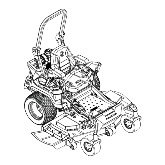
Page 16: Controls And Features
CONTROLS AND FEATURES Figure 10 1. Fuel Tank and Cap 14. Deck Lift Pedal 2. Fuel Level Window 15. Rollover Protection Structure (ROPS) 3. Oil Filter 16. Seat Adjustment Lever 4. Oil Drain 17. Seat Latch 5. Engine Oil Dipstick 18. -
Page 17: Ignition Key
THROTTLE CONTROL LEVER WARNING: AVOID INJURY. See Figure 13. Read and understand the Controls engine speed. Safety section before proceeding. See Figure 10 for all controls and features locations. Fast IGNITION KEY See Figure 11. Controls power to the engine. The key cannot be removed when in run position. -
Page 18: Transport Lock Release Lever
TRANSPORT LOCK RELEASE PARKING BRAKE LEVER LEVER See Figure 16. See Figure 15. Controls the parking brake. The engine will not start with brake in the off position. Releases deck from transport lock position. Brake Engaged (On) Figure 15 Brake Released (Off) DECK LIFT PEDAL Raises mower deck to change height-of-cut setting. -
Page 19: Operation
4. Check function of the Safety Interlock System by performing the tests in Check Safety Interlock System on page 20. Contact your Ariens dealer for repair if any of the tests fail. 5. Set cutting height. See Figure 17. a. Push mower lift pedal forward until transport lock engages. -
Page 20: Start The Engine
Lower Center Bar START THE ENGINE See Figure 19. 1. Push PTO knob down to off position. 2. Move steering levers to neutral position. WARNING: AVOID INJURY. 3. Engage parking brake. Lower the center bar only 4. If engine is cold, pull choke knob up to on when needed to drive under position. -
Page 21: Stop The Engine
STOP THE ENGINE Direction Lever Position of Travel WARNING: AVOID INJURY. Forward Push both levers Wait for all moving parts to forward from stop before leaving operator’s neutral position. position. Reverse Pull both levers 1. Place steering levers in neutral position backward from and rotate outward. -
Page 22: Transport Unit
Proper maintenance can prolong the life of unit. The Maintenance Schedule on page 19 shows the recommended service schedule. Your Ariens dealer can provide service and adjustments to keep your unit operating at peak efficiency. Contact an authorized engine manufacturer’s service center for engine service. -
Page 23: Maintenance Schedule
SERVICE PARTS See your Ariens dealer to purchase service parts for your unit. Description Qty. Part No. Transaxle Drive Belt 07225600 Mower Belt – Left 60" 07200817 Mower Belt – Right 60" 07200807 Mower Blade – 60" 03253900 Seat Switch 02754100 Hydraulic Oil –... -
Page 24: Hour / Maintenance Meter
Check function of the Safety Interlock System Hour meter measures engine runtime and by performing the tests below. Contact your cannot be reset. Ariens dealer for repair if any of the tests fail. Maintenance Models Test Steering PTO Parking Result See Figure 23. -
Page 25: Check Tire Pressure
CHECK TIRE PRESSURE CHECK MOWER BLADES See Specifications on page 39 for Check blades for wear. Replace or sharpen recommended tire pressure. as needed. CAUTION: AVOID INJURY. Use WARNING: AVOID INJURY. sturdy gloves or padding to Explosive separation of tire protect hands when working with and rim parts is possible. -
Page 26: Battery Service
BATTERY SERVICE DO NOT sharpen to this pattern. WARNING: Battery posts, terminals and related accessories contain lead and lead compounds, chemicals known to the State of California to cause cancer and reproductive harm. Wash hands after handling. Remove Battery Sharpen to this pattern. Remove Factory Battery 1. -
Page 27: Check Mower Belts
4. Return seat to operating position Jump Starting Install U1 Battery 1. Reinstall positive cable and then the Ariens does not recommend jump starting negative cable. your unit. Jump-starting can damage engine and system components. Refer to engine 2. Insert T bracket through upper slots in manual for details. - Page 28 1. Cold Fill Line Figure 29 2. Operate engine for 1 minute and recheck Figure 30 oil levels. 3. Add hydraulic oil, if needed. 6. Wipe filter-mounting surface clean. a. Remove expansion tank caps. 7. Lubricate rubber gasket on new oil filter with clean hydraulic oil.
-
Page 29: Service & Adjustments
3. Support unit so drive wheels are off the ADJUST STEERING LEVERS ground. Adjust Height 4. Bypass transaxles. See Move Unit The steering lever height may be adjusted for Manually on page 17. operator comfort. 5. Start the engine and slowly move steering See Figure 32. -
Page 30: Adjust Unit To Drive Straight
If there is more than 3.2 mm (1/8") between NOTICE: Reverse travel can only be the horizontal alignment of the steering adjusted by your Ariens dealer. levers, align the levers. Adjust Tire Pressure 6. Stop engine, remove key and wait for 1. -
Page 31: Adjust Transaxles
Adjust Neutral Position If wheel hub has excessive rotation after checking for excessive creep, adjust neutral position. 1. Loosen the return-to-neutral screw on the transaxle. See Figure 36. Figure 35 3. Align steering levers. See Adjust Steering Levers on page 25. Figure 36 ADJUST TRANSAXLES Check For Excessive Creep... -
Page 32: Electrical Service
6. Check wheel hubs for rotation. REPLACE MOWER BELTS • If there is only slight rotation, stop CAUTION: Damage or worn engine, reinstall wheels, return unit to belts may result in injury and / or operating position and advance to damage to the unit. - Page 33 Install Mower Drive Belt See Figure 42. 1. Install mower drive belt around bottom groove of split pulley at deck center and around bottom groove of right spindle pulley. 2. Reinstall idler spring hook around anchor bolt to apply tension to belt. 1.
-
Page 34: Replace Transaxle Drive Belt
3. Under unit, slowly remove spring hook from anchor bolt to release transaxle idler tension. See Figure 45. Figure 43 IMPORTANT: Make sure belt has tension and is aligned in all pulleys. See Figure 44. 1. Spring 2. Anchor Bolt 3. - Page 35 5. Remove transaxle drive belt from drive IMPORTANT: Make sure belt has tension and system in the following order: is aligned in all pulleys. See Figure 48. a. From right transaxle sheave. b. From left transaxle sheave. c. From clutch sheave. Install Transaxle Drive Belt See Figure 47.
-
Page 36: Reverse Clutch Brake Plates
REVERSE CLUTCH BRAKE ADJUST PARKING BRAKE PLATES LEVER See Figure 50. See Figure 52. 1. Remove hardware securing brake plates 1. Place unit in service position. See to clutch bracket. Retain for reinstallation. Service Position on page 18. 2. Reverse the brake plates and secure to 2. - Page 37 5. Slowly disconnect lift-assist springs from 4. Remove hardware retaining deck lift links spring peg on each side of deck. See to deck lift brackets. See Figure 55. Figure 53. Figure 55 1. Lift-Assist Spring 5. Remove deck from under unit. 2.
-
Page 38: Level And Pitch Mower Deck
LEVEL AND PITCH MOWER Level Mower Deck See Figure 59. DECK 1. Lower the high side of deck: IMPORTANT: Make sure unit is on a flat, level surface and that tires are inflated to the a. Loosen jam nuts against deck- recommended pressures. - Page 39 Adjust Blade Pitch IMPORTANT: Side-to-side deck heights MUST remain level even after completing pitch adjustment. IMPORTANT: Pitching the front of the blades lower than the rear provides a balance between cut quality and the power needed to cut grass. Certain cutting conditions require the deck rear to be pitched lower than the front.
-
Page 40: Troubleshooting
Connect spark plug wire(s) or replace spark plug(s) are faulty. spark plug(s). Refer to engine manual. Electrical system is faulty. Contact your Ariens dealer. Engine is faulty. Contact your Ariens dealer. Choke control knob is in on Move knob to off position. - Page 41 TROUBLESHOOTING Problem Probable Cause Correction Mower blades not level or mower Level and adjust pitch of mower deck. deck pitch is incorrect. See Level and Pitch Mower Deck on page 34. Mower blades are dull or faulty. Sharpen or replace mower blades. See Sharpen Blades on page 21.
-
Page 42: Storage
STORAGE ACCESSORIES See your Ariens dealer for a complete list of SHORT-TERM STORAGE compatible accessories and attachments for IMPORTANT: NEVER wash unit with high- your unit. pressure water or store outdoors. Description Part No. 1. Allow unit to cool and clean with mild soap and water. -
Page 43: Specifications
SPECIFICATIONS Model Number 991314 Zenith 60 Description Kawasaki FX 730V Engine 726 (44.3) Engine Displacement – cm Maximum RPM – No Load 3150 Oil Capacity Refer to engine manual. Liquid or Air Cooled Transmission Type Hydrostatic Drive 15W-50 synthetic motor oil (Gravely p/n... - Page 44 CE Sound and Vibration (Ref. EN ISO 5395-3:2013 + A1:2017 + A2:2018) Oper. Ear Sound Pressure (Lpa) in db(A) Uncertainty in db(A) 2.55 Measured Sound Power Level (Lwa) in db(A) Uncertainty in db(A) Guaranteed Sound Power Level (Lwa) in db(A) 2.55 Vibration Measure (m/s ) at Operator Hands...
-
Page 45: Warranty
“Commercial Use.” If any product is rented or leased, then the duration of these warranties shall be 90 days after the date of purchase. An authorized Ariens dealer will repair any defect in material or workmanship, and repair or replace any defective part, subject to the conditions, limitations and exclusions set forth herein. Such repair or replacement will be free of charge (labor and parts) to the original purchaser;... - Page 46 Exclusions – Items Not Covered by This Warranty • Parts that are not genuine Ariens service parts are not covered by this warranty and may void the war- ranty if the parts result in premature wear or damage to the product.
- Page 47 Parts and Accessories Service replacement parts and non-serialized accessories are warranted for 90 days from date of purchase. Parts and accessories must be installed by an authorized Ariens dealer to be covered. Labor is not included. Customer Responsibilities Register the product immediately at the time of sale. If the dealer does not register the product, the customer must register the unit on-line at www.ariens.com.
- Page 48 Disclaimer AriensCo may from time to time change the design of its products. Nothing contained in this warranty shall be construed as obligating the AriensCo to incorporate such design changes into previously manufactured products, nor shall such changes be construed as an admission that previous designs were defective. Limitation of Remedy and Damages AriensCo liability under this warranty, and under any implied warranty that may exist, is limited to repair of any defect in workmanship, and repair or replacement of any defective part.
- Page 50 655 West Ryan Street Brillion, WI 54110 www.ariensco.com...
Need help?
Do you have a question about the 991314 and is the answer not in the manual?
Questions and answers