Table of Contents
Advertisement
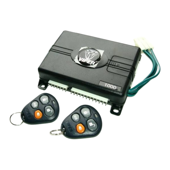
1 1 0 0 0 0 0 0 M M o o d d e e l l
I I n n s s t t a a l l l l a a t t i i o o n n G G u u i i d d e e
NOTE:
This product is intended for installation by a professional installer only!
Any attempt to install this product by any person other than a trained professional
may result in severe damage to a vehicle's electrical system and components.
© 2005 Directed Electronics, Inc. Vista, CA
N3101V 02-05
Advertisement
Table of Contents

Related Manuals for Directed Electronics VIPER 1000


Summary of Contents for Directed Electronics VIPER 1000
- Page 1 This product is intended for installation by a professional installer only! Any attempt to install this product by any person other than a trained professional may result in severe damage to a vehicle’s electrical system and components. © 2005 Directed Electronics, Inc. Vista, CA N3101V 02-05...
- Page 2 ® Trademarks of Directed Electronics, Inc. w w w w w w . . d d i i r r e e c c t t e e c c h h s s . . c c o o m m D D i i r r e e c c t t F F a a x x 8 8 0 0 0 0 - - 9 9 9 9 9 9 - - 1 1 3 3 2 2 9 9 T T e e c c h h n n i i c c a a l l S S u u p p p p o o r r t t 8 8 0 0 0 0 - - 7 7 5 5 3 3 - - 0 0 8 8 0 0 0 0 These resources are for authorized Directed Dealer use only.
-
Page 3: Table Of Contents
D D i i a a g g n n o o s s t t i i c c s s ....................................................3 3 3 3 Arm/Disarm Diagnostics......................33 © 2005 Directed Electronics, Inc. - Page 4 W W i i r r i i n n g g Q Q u u i i c c k k R R e e f f e e r r e e n n c c e e G G u u i i d d e e ........................................3 3 9 9 © 2005 Directed Electronics, Inc.
-
Page 5: Primary Harness Wiring Diagram
This output is often used for trunk release. Whenever the button(s) controlling channel two is pressed for 1.5 seconds, this output is activated and will stay activated as long as the transmission continues. Use an external relay to drive circuits requiring more current. © 2005 Directed Electronics, Inc. - Page 6 DOES NOT have any vehicle component grounds attached to it. A screw should only be used when in conjunction with a two-sided lock washer. Under dash brackets and door sheet metal are not acceptable ground points. It is recommended that all security components be grounded at the same location. © 2005 Directed Electronics, Inc.
- Page 7 Zone 1. It can also be used with Directed single-stage sensors. The H1/7 BLUE instant trigger wire can also be used to shunt sensors during operation of auxiliary channels or remote start. (See Bypassing Sensor Inputs section of this guide.) © 2005 Directed Electronics, Inc.
- Page 8 1 to 90 seconds. ➤ ➤ R R e e m m o o t t e e s s t t a a r r t t output (refer to System Features Menu description for additional information). © 2005 Directed Electronics, Inc.
- Page 9 H1/12 ORANGE (-) ground-when-armed output This wire supplies a (-) ground as long as the system is armed. This output ceases as soon as the system is disarmed. It can supply up to 500 mA of current. © 2005 Directed Electronics, Inc.
-
Page 10: Auxiliary Harness Wiring Diagram
H2/4 GRAY/BLACK (-) channel 6 output This wire provides a (-) 200mA output whenever the transmitter button(s) controlling Channel 6 is pressed. This output can be programmed to provide the following types of outputs (see also the Feature Menus section): © 2005 Directed Electronics, Inc. - Page 11 This can be used to pulse the disarm wire of the vehicle's factory anti-theft device. Use a relay to send a (-) or (+) pulse to the disarm wire as shown in the diagrams below. This also outputs with CH2 is activated. This function is programmable ON/OFF. © 2005 Directed Electronics, Inc.
-
Page 12: Relay Harness Wiring Diagram
Type D wiring section in Tech Tip Document 1041 ). This wire also supplies the output for the Comfort Closure feature (if used). © 2005 Directed Electronics, Inc. -
Page 13: Relay Harness Wiring Instructions
A or B wire to the end of the wire that continues to the vehicle’s starter circuit. Note: Factory default setting is normally closed, if wired for normally open you must change the programming. © 2005 Directed Electronics, Inc. -
Page 14: Super Bright Led, 2-Pin White Plug
Since the system features a Valet button, by using the remote transmitter, this button can be well hidden. Consider how the button will be used before choosing a mounting location. Check for rear clearance before drilling a 9/32-inch hole and mounting the button.The © 2005 Directed Electronics, Inc. -
Page 15: Programmer Interface, 3-Pin Black Plug
1. Clean the mounting area with a quality glass cleaner or alcohol to remove any dirt or residue. 2. Plug the receiver/antenna cable into the receiver/antenna. 3. Mount the receiver/antenna using the supplied double-sided tape. 4. Route the receiver/antenna cable to the control module and plug it into the four-pin antenna connector. © 2005 Directed Electronics, Inc. -
Page 16: Optional Sensors, 4-Pin White Plug
0.8 seconds will trigger full alarm sequence and report Zone 4 or Zone 7 for multiplex input. N N O O T T E E : : The ground for the optional sensors is now controlled by the GWA. © 2005 Directed Electronics, Inc. -
Page 17: Light Flash Jumper
When the bypass period ends, if the unit sees ground on the H1/7 BLUE wire, zones 1, 2, 4, and 7 remain bypassed until five seconds after ground is removed from the BLUE © 2005 Directed Electronics, Inc. - Page 18 This can be done using the status output of a Directed Electronics remote engine starting unit as shown in the following diagram: BLUE WIRE H1/7 TO OPTIONAL HOOD/ CONTROL UNIT ZONE 1 INPUT TRUNK PINS OR SENSORS 1N4004 DIODE...
- Page 19 Valet/Program button four times and then press it once more and HOLD it. The siren would chirp seven times to confirm access to the seventh feature. © 2005 Directed Electronics, Inc.
-
Page 20: Menu #1 - Basic Features
Code Hopping ® Code Hopping ® Note: For feature number 1-7, the 3.5 second door lock pulse setting the siren will chirp twice, the 0.4 second door lock pulse setting the siren will chirp three times. © 2005 Directed Electronics, Inc. -
Page 21: Menu #2 - Advanced Features
Immobilizer Circuit (normally closed) Immobilizer Circuit (normally open) 2-12 Hood Trigger (normally closed) Hood Trigger (normally open) 2-13 Dual Sensor Type (On) Dual Sensor Type (Off) 2-14 High Security Disarm (On) High Security Disarm (Off) © 2005 Directed Electronics, Inc. -
Page 22: Menu #3 - Advanced Features
1–180 seconds (30 seconds) Channel 3 Timed 1–90 seconds (30 seconds) Channel 4 Timed 1–90 seconds (30 seconds) Channel 5 Timed 1–90 seconds (30 seconds) Channel 6 Timed 1–90 seconds (30 seconds) Zone 2 Shock adjust level 0–20 © 2005 Directed Electronics, Inc. -
Page 23: Menu #1 - Basic Features
1-6 PANIC WITH IGNITION ON: This step controls whether or not the Panic Mode is available with the ignition on. In some states, there are laws prohibiting a siren from sounding in a moving vehicle. This feature makes the system compliant with these regulations. © 2005 Directed Electronics, Inc. -
Page 24: Menu #2 - Advanced Features
Progressive Multi-Level Arming After arming, immediately press the ARM button again to enter multi-level arming. Press button once 2 light flashes Zone 2 bypassed Press button twice 3 light flashes Zone 4 bypassed © 2005 Directed Electronics, Inc. - Page 25 Some states have laws regulating how many times a security system can trigger before it is considered a nuisance and the vehicle is towed away. © 2005 Directed Electronics, Inc.
- Page 26 When the double pulse unlock feature is turned on, the BLUE/BLACK H2/F wire will supply two pulses instead of a single pulse. This makes it possible to directly interface with double pulse vehicles without any extra parts. © 2005 Directed Electronics, Inc.
-
Page 27: Menu #3 - Advanced Features
3-2 HORN FUNCTION (FULL ALARM ONLY)/SIREN FUNCTION (20mS, 30mS, 40mS, 50mS): Program for output when the alarm is fully triggered or as the siren (arming/disarming and warnaway and full trigger with timing options). © 2005 Directed Electronics, Inc. - Page 28 3-8 CHANNEL 4 LINKING (NONE)/ARM, DISARM, BOTH: See Feature 3-6. 3-9 CHANNEL 5 VALIDITY (ON)/LATCHED/LATCHED, RESET WITH WITH IGNITION/30-SECOND/60-SECOND/90-SECOND TIMED: Refer to discussion for H2/4. 3-10 CHANNEL 5 LINKING (NONE)/ARM, DISARM, BOTH: See Feature 3-6. © 2005 Directed Electronics, Inc.
- Page 29 N N O O T T E E : : If adding a remote, a button must be taught to the unit in the Channel 1 or Channel 4 position prior to programming other channels. © 2005 Directed Electronics, Inc.
- Page 30 5. R R e e l l e e a a s s e e . . Once the code is learned, the Valet/Program button can be released. To exit the learn routine: One long chirp indicates that Learn Routine has been exited. Learn Routine will be exited if any of the following occurs: © 2005 Directed Electronics, Inc.
-
Page 31: Standard Configuration
When programmed for standard configuration, the transmitter buttons are assigned to the following functions: operates Lock, Arm/Panic On/Panic Off operates Unlock, Disarm/Panic Off operates Channel 2 and Silent Mode operates Panic On/Off operate Channel 3 operate Channel 4 operate Channel 5 operate Channel 6 © 2005 Directed Electronics, Inc. -
Page 32: Enter Shock Sensor Adjustment Mode
The siren will chirp 1-time for each step decreased in adjustment. When the shock sensor adjustment reaches minimum sensitivity (sensor is Off) the siren will emit 1 short and then 1 long chirp. © 2005 Directed Electronics, Inc. -
Page 33: Exit Shock Sensor Adjustment Mode
Arm/Disarm Diagnostics The number of siren chirps will indicate the status of the system when arming and disarming. For information on which zone is active or has been violated refer to the Table of Zones . © 2005 Directed Electronics, Inc. - Page 34 Inputs shorter than 0.8 seconds will trigger a Warning Zone response, while inputs longer than 0.8 seconds will instantly trigger the full alarm sequence. NOTE: The Warn Away response does not report on the LED. ® © 2005 Directed Electronics, Inc.
- Page 35 It must be ® ® programmed in the features menu and the Failsafe Starter Kill must be installed for it to work properly. For operational instructions when testing VRS refer to the Owner's Guide. ® ® © 2005 Directed Electronics, Inc.
- Page 36 That’s how the progressive two-stage door input works! This is the instant response feature of ➤ this system. Even if the door is closed immediately, the system provides an instant trigger by chirping, and then progressing to a constant siren. © 2005 Directed Electronics, Inc.
- Page 37 Is it plugged into the correct socket? Check the System Features Learn Routine for the ➤ programmed Valet pulse count. Status LED doesn’t work. Make sure that it is plugged in. (See Plug-In Harnesses section of this guide.) Is the LED ➤ plugged into the correct socket? © 2005 Directed Electronics, Inc.
- Page 38 © 2005 Directed Electronics, Inc.
- Page 39 Wiring Quick Reference Guide 8-Pin H2 Auxiliary Harness Immobilizer 7-Pin H3 Door Lock Harness © 2005 Directed Electronics, Inc.
Need help?
Do you have a question about the VIPER 1000 and is the answer not in the manual?
Questions and answers