Table of Contents
Advertisement
Quick Links
Advertisement
Table of Contents
Troubleshooting

Related Manuals for Miller 1A


Summary of Contents for Miller 1A
- Page 1 OM-626B August 1995 Eff. w/Serial Number KC230971 Processes TIG (GTAW) Welding MIG (GMAW) Welding Description Coolant System For Water-Cooled TIG Torches Or MIG Guns Rated Up To 500 Amperes Radiator 1A And 2A Visit our website at www.MillerWelds.com...
- Page 2 – every power source from This Owner’s Manual is designed to help you get the most out of your Miller is backed by the most Miller products. Please take time to read the Safety precautions. They will hassle-free warranty in the business.
-
Page 3: Table Of Contents
TABLE OF CONTENTS SECTION 1 – SAFETY PRECAUTIONS - READ BEFORE USING ......1-1. -
Page 5: Section 1 - Safety Precautions - Read Before Using
SECTION 1 – SAFETY PRECAUTIONS - READ BEFORE USING som _nd_5/97 1-1. Symbol Usage Means Warning! Watch Out! There are possible hazards with this procedure! The possible hazards are shown in the adjoining symbols. This group of symbols means Warning! Watch Out! possible Y Marks a special safety message. - Page 6 ARC RAYS can burn eyes and skin. BUILDUP OF GAS can injure or kill. D Shut off shielding gas supply when not in use. Arc rays from the welding process produce intense D Always ventilate confined spaces or use visible and invisible (ultraviolet and infrared) rays that can burn eyes and skin.
-
Page 7: Additional Symbols For Installation, Operation, And Maintenance
1-3. Additional Symbols For Installation, Operation, And Maintenance FIRE OR EXPLOSION hazard. MOVING PARTS can cause injury. D Do not install or place unit on, over, or near D Keep away from moving parts such as fans. combustible surfaces. D Keep all doors, panels, covers, and guards D Do not install unit near flammables. -
Page 8: Emf Information
1-5. EMF Information Considerations About Welding And The Effects Of Low Frequency 1. Keep cables close together by twisting or taping them. Electric And Magnetic Fields 2. Arrange cables to one side and away from the operator. Welding current, as it flows through welding cables, will cause electro- magnetic fields. -
Page 9: Section 1 - Consignes De Securite - Lire Avant Utilisation
SECTION 1 – CONSIGNES DE SECURITE – LIRE AVANT UTILISATION som _nd_fre 5/97 1-1. Signification des symboles Signifie Mise en garde ! Soyez vigilant ! Cette procédure présente des risques de danger ! Ceux-ci sont identifiés par des symboles adjacents aux directives. Ce groupe de symboles signifie Mise en garde ! Soyez vigilant ! Il y a des Y Identifie un message de sécurité... - Page 10 LES RAYONS DE L’ARC peuvent pro- LES ACCUMULATIONS DE GAZ ris- voquer des brûlures dans les yeux et quent de provoquer des blessures ou sur la peau. même la mort. Le rayonnement de l’arc du procédé de soudage D Fermer l’alimentation du gaz protecteur en cas de génère des rayons visibles et invisibles intenses non utilisation.
-
Page 11: Dangers Supplémentaires En Relation Avec L'installation, Le Fonctionnement Et La Maintenance
1-3. Dangers supplémentaires en relation avec l’installation, le fonctionnement et la maintenance Risque D’INCENDIE OU DES ORGANES MOBILES peuvent D’EXPLOSION. provoquer des blessures. D Ne pas placer l’appareil sur, au-dessus ou à proxi- D Rester à l’écart des organes mobiles comme le mité... -
Page 12: Principales Normes De Sécurité
1-4. Principales normes de sécurité Safety in Welding and Cutting, norme ANSI Z49.1, de l’American Wel- Safe Handling of Compressed Gases in Cylinders, CGA Pamphlet P-1, ding Society, 550 N.W. Lejeune Rd, Miami FL 33126 de la Compressed Gas Association, 1235 Jefferson Davis Highway, Suite 501, Arlington, VA 22202. -
Page 13: Section 2 - Safety Information
SECTION 2 – SAFETY INFORMATION mod1.1 2/93 Read all safety messages throughout this manual. Obey all safety messages to avoid injury. Learn the meaning of WARNING and CAUTION. Safety Alert Symbol Signal Word WARNING means possible death or serious injury can happen. WARNING CAUTION CAUTION means possible minor... -
Page 14: Coolant System Rating
3-1. Coolant System Rating The cooling capacity curve shows how much heat the unit can remove from incoming coolant. Coolant ca- pacity limited by torch/gun temper- ature rating (see torch/gun owner’s manual). ssb1.1 10/91 – Ref. SB-130 607 Figure 3-1. Heat Dissipation Curve SECTION 4 –... -
Page 15: Selecting A Location
B. Typical GMAW Connections Coolant System Coolant Hoses Obtain hoses with proper fittings (see Section 4-4). GMAW Gun Wire Feeder Gas Cylinder Welding Power Source Welding power source without water valve shown. When using coolant system with a welding power source with a water valve, by-pass water valve on welding power source by connecting directly to torch/gun to... -
Page 16: Coolant Guidelines
Disconnect input power plug from receptacle before ethylene glycol and distilled or deionized water such cleaning system components. as MILLER coolant Part No. 128 705 or equivalent. DO NOT USE AUTOMOTIVE ANTIFREEZE. FAILURE TO PROPERLY MAINTAIN COOLANT SYSTEM can cause damage to the coolant system and torch/gun. -
Page 17: Connecting Coolant Hoses
4-4. Connecting Coolant Hoses CAUTION INCORRECT HOSES will damage unit. • Use hoses compatible with coolant such as Neoprene, Buna-N, Hypalon, or equivalent. • Incorrect hoses will degrade and plug or damage the coolant system. OVERHEATING Gas Tungsten Arc Welding (GTAW) torches and Gas Metal Arc Welding (GMAW) guns can damage torches and guns. -
Page 18: Operating Coolant System
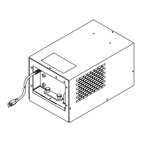
4-6. Operating Coolant System CAUTION PLUGGED OR CLOGGED LINES OR HOSES can cause cooling system damage. • Do not operate coolant system with plugged or clogged lines or hoses. Power Switch Use switch to turn unit On and Off. Flow Indicator Use indicator to check coolant pump operation. -
Page 19: Cleaning Coolant Strainer
5-2. Cleaning Coolant Strainer READ SAFETY BLOCKS at start of WARNING Section 5 before proceeding. Turn Off and unplug unit. Coolant Pump Acorn Nut Place cloth or suitable container un- der nut, and remove nut. Rubber Washer Strainer Rinse strainer with clean water. Reinstall parts. -
Page 20: Adjusting Relief Valve
5-4. Adjusting Relief Valve READ SAFETY BLOCKS at start of WARNING Section 5 before proceeding. If hoses become clogged, the relief valve protects the unit for less than two minutes by returning coolant back to the pump. Relief valve is factory set to open at 60 psi (414 kPa). -
Page 21: Section 6 - Electrical Diagrams
Table 5-1. Coolant System Trouble Trouble Remedy Section Coolant system does not work. Secure power cord plug in power receptacle. Check line fuses or circuit breaker, and replace if necessary. – – Thermal overload. Allow motor to cool. Have Factory Authorized Service Station/Service Distributor –... -
Page 22: Section 7 - Parts List
SECTION 7 – PARTS LIST OM-626 Page 18... - Page 23 Item Dia. Part Mkgs. Description Quantity Figure 7-1. Main Assembly ... . . 135 804 PUMP, coolant (consisting of) ......... .
- Page 24 Notes...
- Page 25 Notes...
-
Page 26: Options And Accessories
Its primary use is in ethylene glycol and deionized also be used in MIG systems MIG products, such as the Miller water to protect against freezing to where aluminum is not in the water water-cooled XR, which has an 37°F (–38°C) or boiling to 227°F... - Page 27 Effective January 1, 2000 (Equipment with a serial number preface of “LA” or newer) This limited warranty supersedes all previous Miller warranties and is exclusive with no other Warranty Questions? guarantees or warranties expressed or implied. Call LIMITED WARRANTY – Subject to the terms and conditions APT, ZIPCUT &...
- Page 28 Distributor Address City State For Service Call 1-800-4-A-Miller or see our website at www.MillerWelds.com to locate a DISTRIBUTOR or SERVICE AGENCY near you. Always provide Model Name and Serial/Style Number. Contact your Distributor for: Welding Supplies and Consumables Options and Accessories...
Need help?
Do you have a question about the 1A and is the answer not in the manual?
Questions and answers