Advertisement
PR-330A
Y AMI D
R
POWER
ON
OFF
STANDBY
BASS
0
2
2
2
4
4
4
MUTE
6
6
6
8
8
8
10
10
10
PHONES
100W+100W
TREBLE
POWERFUL AMPLIFIER SYSTEM
0
2
4
6
8
10
TAPE
AUX
REMOTE SENSOR
REMOTE SENSOR
AV1/AV2
CD
TUNER
U.S.A.
VOLUME
EXTERNAL
EXTERNAL
PRESET EQ
PRESET EQ
PROCESSOR
PROCESSOR
MIC
MIC LEVEL
MIC LEVEL
MIN
MAX
Advertisement
Table of Contents

Related Manuals for Pyramid PR330A


Summary of Contents for Pyramid PR330A
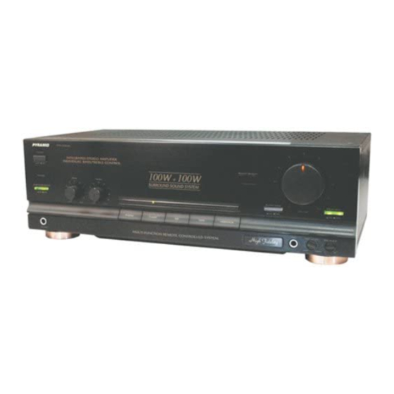
- Page 1 PR-330A Y AMI D POWER STANDBY BASS TREBLE MUTE PHONES 100W+100W POWERFUL AMPLIFIER SYSTEM TAPE AV1/AV2 VOLUME REMOTE SENSOR REMOTE SENSOR PRESET EQ PRESET EQ PROCESSOR PROCESSOR TUNER MIC LEVEL MIC LEVEL U.S.A. EXTERNAL EXTERNAL...
- Page 2 PRECAUTIONS Thank you for purchasing this HI-FI product. Taking time to read these operating instructions carefully before use will acquaint you fully with all its features and help ensure optimum performance. In order to simplify the explanation illustrations may sometimes differ from the originals. RISK OF ELECTRIC SHOCK DO NOT OPEN CAUTION: TO REDUCE THE RISK OF ELECTRIC SHOCK,...
- Page 3 CONNECTIONS FOR INTEGRATED STEREO AMPLIFIER Refer to page 4 the connection diagram as you read the following. Connection precautions When connecting, either disconnect the power plug from the power outlet or turn off the unit’s power using the POWER switch. Check the left and right channels and connect properly (Left to L and Right to R).
- Page 4 CONNECTIONS Speaker systems Connect the speaker systems to the SPEAKERS terminals on the rear panel of the unit with the speaker cords. When viewed from the front (the listening position), the speaker mounted on the left should be connected to the L terminals, and the speaker mounted on the right should be connected to the R terminals.
-
Page 5: Connection Diagram
CONNECTION DIAGRAM 75Ω RE M OTE SYS TEM TAPE TUNER TUNER AUDI O REMOTE SYSTEM TO AMP VOL TAGE SELECTOR 110~120V 60Hz ANTENNA OUTPUT Loop REMOTE SYSTEM TO AMP RIGHT LE FT INTEGRATED CIR CU IT TAPE AC 22 0V - 2 30V ~ 50Hz... -
Page 6: Panel Information
PANEL INFORMATION POWER SWITCH Power is supplied to the amplifier when this switch is depressed and the power is switched off when the switch is released. INDICATOR DISPLAY Press either TAPE, AUX, AV1/AV2, CD or TUNER, the relative indicator will be grown. REMOTE SENSOR Work with the remote control. -
Page 7: Operating Procedures
OPERATING PROCEDURES Before starting operation Check that the controls have been set to the following positions before commencing operation Rotate the VOLUME control counterclockwise as far as it will go and set it at the “0” minimum volume position. Set the BASS and TREBLE tone controls to the “0” (center) position. -
Page 8: Operation
OPERATION REMOTE CONTROL R EM O TE CO N TR O L P R -3 3 0 A (1) Power Button (2) AM/FM Selector/Memory Scan/Hold (3) Volume Control Key (+ -) (4) Equalizer Sound preset (5) Equalizer User Preset (6) CD Control Key * STOP... -
Page 9: Specifications
Signal to noise ratio (short-circuit, A-network) TUNER, TAPE PLAY….70 dB Power requirements Power voltage…….220V--230V--50Hz For U.K………240V, 50Hz For U.S.A & Canada…..110V, 60 Hz Power consumption……watts VA Rated Watts maximum Dimensions………..420 x 135 x 230mm (W x H x D) Weight………………6.2 Kg...
Need help?
Do you have a question about the PR330A and is the answer not in the manual?
Questions and answers