
Related Manuals for Masterweld 301 PLUS


Summary of Contents for Masterweld 301 PLUS
- Page 1 Cod.006.0001.1319 25/11/2013 v2.7 ENGLISH Masterweld 301 PLUS Instruction manual...
- Page 2 Cod.006.0001.1319 25/11/2013 v2.7 Masterweld 301 PLUS ENGLISH 2/28...
-
Page 3: Table Of Contents
PARAMETERS SETTING: SPEED LIMIT ..................................19 4.7.6 ADJUSTMENT WELDING PARAMETERS PANEL ..............................20 TECHNICAL DATA ....................................21 SPARE PARTS ..................................... 23 WIRE FEED MOTOR .................................... 25 WIRE FEEDER ROLLS ..................................26 ELECTRICAL DIAGRAM ..................................27 MICROMAG 301 PLUS ..................................27 3/28... -
Page 4: Introduction
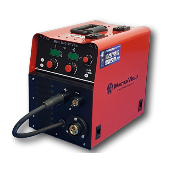
ENGLISH INTRODUCTION INTRODUCTION IMPORTANT! The Masterweld 301 PLUS is a compact and heavy duty generator for This handbook must be consigned to the user prior to MIG/MAG welding. installation and commissioning of the unit. The reduced weight and compact size allow it to be carried wherever Read the "General prescriptions for use"... -
Page 5: Installation
Cod.006.0001.1319 Masterweld 301 PLUS 25/11/2013 v2.7 ENGLISH INSTALLATION DANGER! REAR PANEL Lifting and positioning Read the warnings highlighted by the following symbols in the “General prescriptions for use”. CONNECTIONS TO THE ELECTRICAL MAINS NETWORK The characteristics of the mains power supply to which the equipment shall be connected are given in the section entitled “Technical data”... -
Page 6: Preparing For Mma Welding
Cod.006.0001.1319 25/11/2013 v2.7 Masterweld 301 PLUS ENGLISH 10. Set the required welding parameter values on the user interface. The system is ready to start welding. Preparing for MMA (polarity to basic electrode) Wire feed motor power transformer fuse. Type: Delayed acting (T) -
Page 7: Preparing For Tig Welding
Cod.006.0001.1319 Masterweld 301 PLUS 25/11/2013 v2.7 ENGLISH PREPARING FOR TIG WELDING Preparing for TIG (polarity for tungsten electrode) 1. Set the welding power source ON/OFF switch to “O” (unit de- energized). 2. Plug the power cable plug into a mains socket outlet. -
Page 8: Preparing For Mig/Mag Welding
Cod.006.0001.1319 25/11/2013 v2.7 Masterweld 301 PLUS ENGLISH PREPARING FOR MIG/MAG WELDING 2.6.1 WIRE SPOOL POSITIONING 1. Open the unit side door to gain access to the spool compartment. 2. Unscrew the cap of the spool holder. 2.6.2 POSITIONING THE WIRE IN THE WIRE FEEDER 1. -
Page 9: Connections To Sockets
Cod.006.0001.1319 Masterweld 301 PLUS 25/11/2013 v2.7 ENGLISH 5. Feed the wire between the wire feeder rolls and insert it into the 2.6.3 CONNECTIONS TO SOCKETS MIG/MAG TORCH connector plug. 1. Set the welding power source ON/OFF switch to “O” (unit de- 6. - Page 10 Preparing for MIG/MAG The above diagram shows the MIG welding torch to be the Masterweld MW300. Although lightweight this torch has a 300 amp bicox cable, designed to withstand the amperage capacity and the OCV (Open Circuit Voltage) of the machine. We recommend the use of this torch best arc characteristics and consumable life.
-
Page 11: Commissioning
Cod.006.0001.1319 Masterweld 301 PLUS 25/11/2013 v2.7 ENGLISH COMMISSIONING USER INTERFACE CODE SYMBOL DESCRIPTION This LED illuminates to show an anomaly in the operating conditions. See § 3.5 ALARMS MANAGEMENT page 14. Illumination of this LED indicates the display of the average voltage and current value measured during the final moments of welding. - Page 12 Cod.006.0001.1319 25/11/2013 v2.7 Masterweld 301 PLUS ENGLISH CODE SYMBOL DESCRIPTION This button opens the gas solenoid valve to fill the circuit and calibrate the pressure with the regulator on the gas cylinder. POST-GAS adjustment Hold down the button for 3 seconds to open the menu. (See § 4.6.2 page 18.) MIG/MAG mode: this button activates wire feed to insert it through the MIG/MAG torch.
-
Page 13: Unit Power-Up
Cod.006.0001.1319 Masterweld 301 PLUS 25/11/2013 v2.7 ENGLISH UNIT POWER-UP Set the welding power source ON/OFF switch to “I” to switch on the unit. The message appears for a few seconds on the following displays: D1-D2 AL.HEA. First power-up or power-ups following a RESET procedure The welding power source sets up for welding with the factory presets. -
Page 14: Gas Flow Adjustment
Cod.006.0001.1319 25/11/2013 v2.7 Masterweld 301 PLUS ENGLISH GAS FLOW ADJUSTMENT When the unit is powered on the solenoid valve opens for 1 second. This serves to fill the gas circuit. Open the gas solenoid valve by pressing and releasing the button. -
Page 15: Welding Settings
Cod.006.0001.1319 Masterweld 301 PLUS 25/11/2013 v2.7 ENGLISH WELDING SETTINGS TORCH TRIGGER MODES 2 STROKE LIFT-ARC TIG WELDING (2T) 1. Touch the workpiece with the torch electrode. 2. Press (1T) and keep the torch trigger pressed. 3. Slowly lift the torch to strike the arc. -
Page 16: Selection Of The Welding Mode And Torch Trigger Procedure
Cod.006.0001.1319 25/11/2013 v2.7 Masterweld 301 PLUS ENGLISH SELECTION OF THE WELDING MODE AND TORCH TRIGGER PROCEDURE SEL1 Use this selector to select one of the following welding modes. Use this button to select one of the following torch trigger procedures. -
Page 17: Welding Parameters
Cod.006.0001.1319 Masterweld 301 PLUS 25/11/2013 v2.7 ENGLISH WELDING PARAMETERS WELDING CURRENT INDUCTANCE Output current value during welding. Consequences of a higher value: - "Softer welding". HOT-START - Less spatter. - Less positive starting. This parameter aids electrode melting at the time of arc striking. -
Page 18: Electrode Welding (Mma)
Cod.006.0001.1319 25/11/2013 v2.7 Masterweld 301 PLUS ENGLISH ELECTRODE WELDING (MMA) SEL1 Select the following welding mode on the selector located in the spool compartment: MMA The message appears on the following displays: D2 4.5.1 PARAMETERS SETTING: WELDING CURRENT Using the potentiometer, edit the value of the parameter. -
Page 19: Mig/Mag Welding
Cod.006.0001.1319 Masterweld 301 PLUS 25/11/2013 v2.7 ENGLISH MIG/MAG WELDING SEL1 Select the following welding mode on the selector located in the spool compartment: MIG/MAG 4.7.1 PARAMETERS SETTING: MIG/MAG WELDING VOLTAGE POT3 Using the potentiometer, edit the value of the parameter. -
Page 20: Adjustment Welding Parameters Panel
Cod.006.0001.1319 25/11/2013 v2.7 Masterweld 301 PLUS ENGLISH 4.7.6 ADJUSTMENT WELDING PARAMETERS PANEL The picture shows the adjustment panel of MIG/MAG welding parameters, accessible by opening the wire feeding unit door. If the panel is not enabled, the microprocessor automatically assigns the default value to the parameters. -
Page 21: Technical Data
Cod.006.0001.1319 Masterweld 301 PLUS 25/11/2013 v2.7 ENGLISH TECHNICAL DATA 2002/96/EC-Waste electrical and electronic equipment (WEEE) 2004/108/EC-Electromagnetic compatibility (EMC) Directives applied 2006/95/EC-Low voltage (LVD) 2011/65/EU-Restriction of the use of certain hazardous substances (RoHS) Construction standards EN 60974-1; EN 60974-5; EN 60974-10 Class A... - Page 22 Cod.006.0001.1319 25/11/2013 v2.7 Masterweld 301 PLUS ENGLISH 40 % (40° C) 8.0 A 60 % (40° C) 8.2 A 100 % (40° C) 8.8 A 50 % (40° C) 6.2 A Maximum effective supply current 60 % (40° C) 6.4 A 100 % (40°...
-
Page 23: Spare Parts
Cod.006.0001.1319 Masterweld 301 PLUS 25/11/2013 v2.7 ENGLISH SPARE PARTS 23/28... - Page 24 Cod.006.0001.1319 25/11/2013 v2.7 Masterweld 301 PLUS ENGLISH N° CODE DESCRIPTION 045.0006.0052 COPPER BRACKET (NEGATIVE POLE) 045.0002.0005 SUPPLY CABLE 011.0009.0121 TRANSFORMER SUPPORT PLATE 011.0009.0119 FAN COVER REAR PLATE 011.0002.0018 SOLENOID VALVE PLATE 040.0001.0015 THREE-POLE SWITCH 011.0009.0127 INTERNAL PLATE 016.0011.0007 CAP Ø= 11 002.0000.0284...
-
Page 25: Wire Feed Motor
Cod.006.0001.1319 Masterweld 301 PLUS 25/11/2013 v2.7 ENGLISH WIRE FEED MOTOR 25/28... -
Page 26: Wire Feeder Rolls
Cod.006.0001.1319 25/11/2013 v2.7 Masterweld 301 PLUS ENGLISH N° CODE DESCRIPTION 002.0000.0205 COMPLETE PRESSURE ARM 002.0000.0203 COMPLETE PRESSURE DEVICE 002.0000.0201 MOTOR COIL 002.0000.0259 INLET GUIDE WITH SOFT LINER 002.0000.0202 FEED PLATE 002.0000.0266 GUARD SAFETY KIT 002.0000.0212 INSULATION MOUNTING KIT 002.0000.0209 GEAR ADAPTOR FEED ROLL 002.0000.0210... -
Page 27: Electrical Diagram
Cod.006.0001.1319 Masterweld 301 PLUS 25/11/2013 v2.7 ENGLISH ELECTRICAL DIAGRAM MICROMAG 301 PLUS 27/28... - Page 28 Cod.006.0001.1319 25/11/2013 v2.7 Masterweld 301 PLUS ENGLISH 28/28...
Need help?
Do you have a question about the 301 PLUS and is the answer not in the manual?
Questions and answers