
Related Manuals for GE Fuji Electric FVR-C9S-2UX Series


Summary of Contents for GE Fuji Electric FVR-C9S-2UX Series
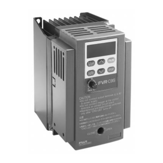
- Page 1 sales@artisantg.com artisantg.com (217) 352-9330 | Click HERE Find the Fuji Electric FVR001C9S-2UX at our website:...
- Page 2 FVR-C9S-2UX Instruction Manual FVR-C9S-2UX Drive Series Three-phase 230 V AC Input Type Artisan Technology Group - Quality Instrumentation ... Guaranteed | (888) 88-SOURCE | www.artisantg.com...
- Page 3 FVR-C9S-2UX CAUTION • Make sure that you read this instruction manual thoroughly before installing, wiring, operating and inspecting this drive. • Please make sure that this instruction manual accompanies the drive to the end user. • Keep this instruction manual so that it will always be available for the duration of the drive’s operating life.
-
Page 4: Table Of Contents
FVR-C9S-2UX Thank you for purchasing the Fuji “FVR-C9S” drive, marketed by GE Fuji Drives USA, Inc. This instruction manual is included with the drive and equipment and is provided for the convenience of the end user. Please be sure it accompanies the drive. -
Page 5: Safety Precautions
FVR-C9S-2UX Do not let any scraps of thread, paper, sawdust, 0. Safety Precautions dirt, metal shavings or other foreign objects get inside the drive or onto the cooling fins, other- Before carrying out installation, wiring, mainte- wise fire or problems with operation may result. nance or inspection of the drive, read this in- struction manual thoroughly to gain a full under- Do not install and operate the drive if it is dam-... - Page 6 FVR-C9S-2UX CAUTION: CAUTION: Check that the phase and voltage of the AC Do not touch the cooling fins, as they become power supply being connected matches the hot during drive operation. input phase and rated input voltage of the drive. Because it is relatively easy to set the drive to Using an improper power supply may cause high speed operation, be sure to check the...
-
Page 7: Inspection Upon Receipt
FVR-C9S-2UX Field wiring connection shall be made by a UL UL/CSA listed and CSA Certified closed-loop terminal WARNING / AVERTISSEMENT connector sized for the wire gauge involved. Connector must be fixed using the crimp tool Hazard of electrical shock. Disconnect incoming specified by the connector manufacturer. -
Page 8: Part Names
FVR-C9S-2UX 1. Type 3. Warning and Caution Drive Series Improper wiring will result in damage to, and failure of the unit. Please carefully note the F V R F 2 5 C 9 S 2 U X items listed below, and use the unit as indi- Power Series: 230V UX Series cated. -
Page 9: Specifications
FVR-C9S-2UX 4. Specifications Type (FVR _ _ _ C9S-2UX) Applicable motor output [Hp] Rated capacity [kVA] 0.28 0.56 Voltage [V] Three-phase 200-230V 50/60 Hz (Output voltage is proportional to input voltage) Output Rating Rated current 10.0 16.5 Overload current rating 150% 1 min. - Page 10 FVR-C9S-2UX Type (FVR _ _ _ C9S-2UX) Applicable motor output [Hp] Frequency setting Key operation: Setting with UP/DOWN keys Potentiometer: Terminal for 1-5K ohm VR is provided Analog signal: 0-5 VDC 0-10 VDC (input resistance = 22k ohm) Display Run mode Output frequency is displayed.
-
Page 11: External Dimensions
FVR-C9S-2UX 5. External Dimensions 0.24 (6.2) 3.15 (80) 0.26 (6.5) 0.26 (6.5) 2.64 (67) 0.06 (1.5) .06 (1.5) 2 - 0.20 X 0.24 (2 - 5 X 6.2) 0.43 (11) TERMINAL M3.5 0.06 (1.5) 0.39 (10) 2.36 (60) 0.39 (10) DWG 1: FVRF12C9S-2UX to FVROO1C9S-2UX Rated Current External Dimensions: inches (mm) - Page 12 FVR-C9S-2UX 0.24 (6.2) 4.33 (110) 0.24 (6.2) 0.24 (6.2) 3.86 (98) 0.18 (4.5) 0.24 (6.2) 2 - dia. 0.20 (2 - dia. 5) TERMINAL M3.5 0.20 (5) 0.43 (11) 0.45 (11.5) 0.45 (11.5) 3.43 (87) DWG 2: FVR002C9S to FVR003C9S-2UX Rated Current External Dimensions: inches (mm) DWG No.
- Page 13 FVR-C9S-2UX External Dimensions cont. 0.24 (6.2) 5.45 (138.5) 2.87 (73) 2.58 (65.5) 5.51 (140) 0.24 (6.2) 0.24 (6.2) 5.04 (128) 2.09 (53) 0.49 (12.5) 0.71 (18) 0.24 (6.2) 2 - dia. 0.20 (2 - dia. 5) 3.37 (85.5) TERMINAL M4 0.20 (5) 0.43 (11) 0.47 (12)
-
Page 14: Installation Instructions
FVR-C9S-2UX 6. Installation Instructions Mounting plate: Heat sink temperature will reach +90°C during operation. Please use thermostable material for drive mounting Installation Conditions plate. Install the drive in a location which meets the Multi-mounting: When 2 or more drives are following requirements: installed within the drive switchboard, ar- •... - Page 15 FVR-C9S-2UX 5) Reinstall the cover. Connect the harness Disconnect of the keypad panel to the CN2 on the main CN 1 unit, then reinstall the keypad panel fitting it onto the guide pins. CN 2 Connect Guide Pin CN 1 CN 2 CN 2 CRG Lamp...
-
Page 16: Basic Wiring Diagrams
FVR-C9S-2UX 8. Basic Wiring Diagrams 1) Keypad Panel Operation From the factory, the drive is set for frequency control by means of the potentiometer control knob on the keypad panel. The RUN/STOP function of the drive is controlled by the RUN/ STOP keys on the keypad panel. - Page 17 FVR-C9S-2UX 2) External Signal Operation Ensure that the connection is as shown below when operating the drive by means of an exter- nal frequency setting potentiometer or contact signal. Thermal Relay Power supply 8 8 8 AC200~230V 50/60Hz 3 Phase Potentiometer for frequency setting E (G)
-
Page 18: Application Of Wiring And Equipment
FVR-C9S-2UX CAUTION: Long wire lengths between the motor and the drive will result in increased capacitance The control circuit terminal wiring should be and leakage current. This may cause earlier kept as far as possible from the main circuit activation of such protective function as wiring to prevent operational error due to overcurrent protection, overheating protec- noise interference. -
Page 19: Terminal Function Explanation
FVR-C9S-2UX 10. Terminal Function Explanation Terminal Function Explanation Classi- Terminal Code Terminal Name Explanation of Function fication Main Commercial power supply input For connection of 3-Phase 200 to 230V commercial power L1, L2, L3 Circuit terminals supply U, V, W Drive Output Terminals For connection of a 3-Phase motor Grounding terminal of drive chassis (case). - Page 20 FVR-C9S-2UX Terminal Function Explanation Classi- Terminal Code Terminal Name Explanation of Function fication Outputs + 10VDC between FM and CM terminals. When Output for frquency setting is equal to the maximum frequency setting, Analog Monitor Motor outputs + 10VDC at 150% current when monitoring output current.
-
Page 21: Operation
FVR-C9S-2UX 11. Operation • The drive is shipped with a factory in- stalled jumper, between FWD-CM. Only forward operation is possible. To enable Pre-Operation Inspection reverse operation remove the jumper from • Check for wiring errors. FWD/CM and install the jumper between •... - Page 22 FVR-C9S-2UX Selecting Operation Method With the FVR-C9S Series, the following methods can be selected to input the RUN/STOP signals and for frequency setting. RUN/STOP Frequency Setting Function Code setting Keypad panel operation UP/DOWN Keys* RUN/STOP Keys Analog signal (DC0 - 10V) Terminal operation (operation by external UP/DOWN Keys*...
-
Page 23: Keypad Panel
FVR-C9S-2UX 12. Keypad Panel Part Names and Functions RUN key: This key is Digital monitor: used for starting In program mode, the key- 8. 8. 8. operation. The LED pad displays the various (green) lights up function codes and data during operation. - Page 24 FVR-C9S-2UX 4) Function setting method Method Operation Procedure Display Press this key to switch to the PRG/RESET program setting mode. 6 0. 0 Press UP key or DOWN key to UP/DOWN select function code Press this key to display function FUNC/DATA code.
-
Page 25: Function Explanation
FVR-C9S-2UX 13. Function Explanation Function Code Tables Change Function Min. Factory Function Date Code Range Unit During Code Set. Setting Operation 0: Data change possible Data protection — — 1: Data change not possible Frequency 0: Keypad panel (UP/DOWN keys) —... - Page 26 FVR-C9S-2UX Function Code Tables Change Function Min. Factory Function Date Code Range Unit During Code Set. Setting Operation Motor Running 0 - 5 (code) — — Sound The current and previous 3 fault events are displayed Fault Memory — — —...
- Page 27 FVR-C9S-2UX Detailed Explanation of Each Function Code F 0 0 Data Protection The set data can be locked so that it will not be changed by mistake. 0 Data change possible 1 Data change not possible To change data simultaneously press the STOP key and either the UP/DOWN key. F 0 1 Frequency Command Either of the following two frequency setting methods can be selected.
- Page 28 FVR-C9S-2UX F 0 7 Torque Boost Can be set from among 32 different levels in accordance with the type of load, the characteristics of the motor, etc. High For a reduced torque load (fan, pump, etc.) Output voltage 2 Low 1 High Output frequency f 8 Set to match this when using a Fuji FV motor designed for use with a drive.
- Page 29 FVR-C9S-2UX Derating characteristics for the continuously allowable current 1) For a standard 4-pole motor _ _ 1 2) for a forced-air cooled motor _ _ 2 Setting value Setting value 105% 110 - 110 - 105% 100 - 100 - 90 - 90 - 80 -...
- Page 30 FVR-C9S-2UX F 1 0 Restart After Momentary Power Failure It is possible to select whether or not to restart operation when power supply is resumed after momentary power failure. 0 Inactive While stopped: Stopped condition is maintained even after power supply has been restored.
- Page 31 FVR-C9S-2UX F 1 4 Starting Frequency The starting frequency can be set in increments of 1 Hz within a range of 1 to 6 Hz. Note that stopping will also occur at the frequency set by this function. 1 1 Hz 6 6 Hz Set to 2 Hz when using a high speed motor.
- Page 32 FVR-C9S-2UX F 1 7 Data Initialization Reset the data for all of the functions to the value set at the factory. 0 Inactive 1 Resets to the value set at the factory. From the _ _ 0 display, by simultaneously pressing STOP and UP, the display will change to _ _ 1. By pressing FUNC/DATA in this state, the data will be reset to the value set at the factory, and the mode will automatically change to the 6 0.
- Page 33 FVR-C9S-2UX F 2 4 High Limiter F 2 5 Low Limiter The upper and lower and lower limits of the output frequency can be set. 0 Set as a percentage of the maximum frequency in increments of 1% within a range of 0 to 100% If the value set for low limiter is higher than that set for the 100% High...
- Page 34 FVR-C9S-2UX F 2 9 Multistep Speed Setting 1 (Speed 1) F 3 0 Multistep Speed Setting 2 (Speed 2) F 3 1 Multistep Speed Setting 3 (Speed 3) Multistep speeds can be set within a range of 0 to 120 Hz only by changing the contact signal from outside. (X1-CM X2-CM).
- Page 35 FVR-C9S-2UX F 3 2 FM Terminal Output Level Calibration Adjust the level of the voltage output to terminal FM for the frequency meter. 0 Approximate DC 6.5V at full scale 9 Approximate DC 10.3V at full scale Note: The FM terminal output is a pulse output of which frequency is constant (38.1 Hz) and duty is variable. F 3 3 FM Terminal Function Selection With regard to the data outputted to the FM terminal, either the output frequency or the output current can be selected.
-
Page 36: Protective Functions
FVR-C9S-2UX 14. Protective Functions Explanation Display Function Alarm Output Momentary Stops drive to protect it against overcurrent . Overcurrent OC1 = During acceleration Protection OC2 = During deceleration OC3 = During constant speed operation Overvoltage Detects overvoltage of DC intermediate circuit and stops drive. Protection Undervoltage Detects undervoltage of DC intermediate circuit and stops drive. -
Page 37: Warranty Parts And Service
36 of this instruction book. GE Fuji Drives USA, Inc. Out-of-Warranty Procedures 1-540-387-5739 If a defective drive is out-of-warrant contact an Authorized GE Fuji Service Provider for 24-hour Emergency 1-540-387-8292 repair or an Authorized GE Fuji Distributor for replacement. Warranty Coverage... - Page 38 FVR-C9S-2UX In-Warranty Failure Checklist To assist with warranty troubleshooting, the following information is required. This data is needed to evaluate the cause in an effort to eliminate any further failures. Model No.: Serial No.: Start-Up Date: Failure Date: Status When Failure Occurred (check one): Power-Up Running Accel...
- Page 39 FVR-C9S-2UX Notes: Artisan Technology Group - Quality Instrumentation ... Guaranteed | (888) 88-SOURCE | www.artisantg.com...
- Page 40 FVR-C9S-2UX Notes: Artisan Technology Group - Quality Instrumentation ... Guaranteed | (888) 88-SOURCE | www.artisantg.com...
- Page 41 FVR-C9S-2UX GE Fuji Drives USA, Inc. 1501 Roanoke Blvd. Suite 435 Salem, VA 24153 1-800-543-6196 Internet Address: http://www.ge.com Si47-0461 (4/98) Printed in USA Artisan Technology Group - Quality Instrumentation ... Guaranteed | (888) 88-SOURCE | www.artisantg.com...
Need help?
Do you have a question about the Fuji Electric FVR-C9S-2UX Series and is the answer not in the manual?
Questions and answers