
Subscribe to Our Youtube Channel
Related Manuals for King Canada KC-110N


Summary of Contents for King Canada KC-110N
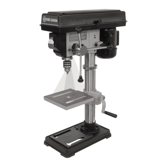
- Page 1 10” BENCH DRILL PRESS 03/2016 INSTRUCTION MANUAL MODEL: KC-110N COPYRIGHT © 2015 ALL RIGHTS RESERVED BY KING CANADA TOOLS INC.
-
Page 2: Warranty Information
King Canada service center. Contact your retailer or visit our web site at www.kingcanada.com for an updated listing of our authorized service centers. In cooperation with our authorized serviced center, King Canada will either repair or replace the product if any part or parts covered under this warranty which examination proves to be defective in workmanship or material during the warranty period. -
Page 3: General Safety Instructions For Power Tools
GENERAL SAFETY INSTRUCTIONS FOR POWER TOOLS 1. KNOW YOUR TOOL footwear is recommended. Wear protective hair covering to con- tain long hair. Roll up long sleeves above the elbows. Read and understand the owners manual and labels affixed to the 12. -
Page 4: Electrical Information
ELECTRICAL INFORMATION WARNING ALL ELECTRICAL CONNECTIONS MUST BE DONE BY A QUALIFIED ELECTRICIAN. FAILURE TO COMPLY MAY RESULT IN SERIOUS INJURY! ALL ADJUSTMENTS OR REPAIRS MUST BE DONE WITH THE MACHINE DISCONNECTED FROM THE POWER SOURCE. FAILURE TO COMPLY MAY RESULT IN SERIOUS INJURY! POWER SUPPLY USING ON/OFF SWITCH WITH REMOVABLE SAFETY KEY WARNING: YOUR DRILL PRESS MUST BE CONNECTED TO A 120V... -
Page 5: Getting To Know Your Drill Press
13. TABLE BEVEL LOCK...locks the table in any position from 0 and millimeters. 7. ON-OFF SWITCH...has a locking feature to prevent unauthorized and possible hazardous use by children and others. Just below it you will MODEL ....................................KC-110N VOLTAGE ......................................120V AMPS ......................................2.5A MOTOR R.P.M....................................1720 Hz/PHASE..................................60 Hz / 1 PHASE... - Page 6 ASSEMBLY BASE, COLUMN & TABLE ASSEMBLY 1. Position the base (A) Fig.6 on the floor. Remove the protective covering and discard. 2. Remove protective sleeve from the column (B) and discard. Place the column assembly on the base, align the holes in the column support (C) with the holes in the base.
-
Page 7: Installing The Head
ASSEMBLY 8. While holding the rack (A) Fig.10 and table support (B) in an engaged position, slide both down over the column (C). Slide rack down the col- umn until the rack is positioned against the lower column support (D). 9. -
Page 8: Assembly And Adjustments
ASSEMBLY & ADJUSTMENTS INSTALLING THE CHUCK 1. Locate the chuck (A) Fig.14 in the box of parts. 2. Clean out the tapered hole in the chuck, also clean the spindle nose (B) with a clean cloth. Make sure there are no foreign particles sticking to the surfaces. The slightest piece of dirt on the spindle nose or the chuck will prevent the chuck from seating properly. -
Page 9: Operation & Adjustments
OPERATION & ADJUSTMENTS WARNING! For your own safety, turn the switch OFF and remove the plug from the power source before making any adjustements. To avoid injury from thrown parts due to the spring release, follow instructions carefully and wear safety glasses. -
Page 10: Operation
OPERATION ADJUSTING THE TABLE SqUARE TO THE HEAD 1. Insert a precision round steel rod (A) Fig.21 approximately 3” long into the chuck and tighten. 2. With the table (B) raised to working height and locked into position, place a combination square (C) flat on the table beside the rod. -
Page 11: Maintenance & Troubleshooting
MAINTENANCE / TROUBLESHOOTING LUBRICATION All of the ball bearings are packed with grease at the factory. They require no further lubrication. Periodically lubricate the splines (Grooves) in the spindle and the rack (Teeth of the quill). WARNING! For your own safety, tur n the switch “OFF” and remove the plug from the power source before maintaining or lubricating your drill press.
Need help?
Do you have a question about the KC-110N and is the answer not in the manual?
Questions and answers