
Related Manuals for King Canada KC-150C


Summary of Contents for King Canada KC-150C
-
Page 1: Instruction Manual
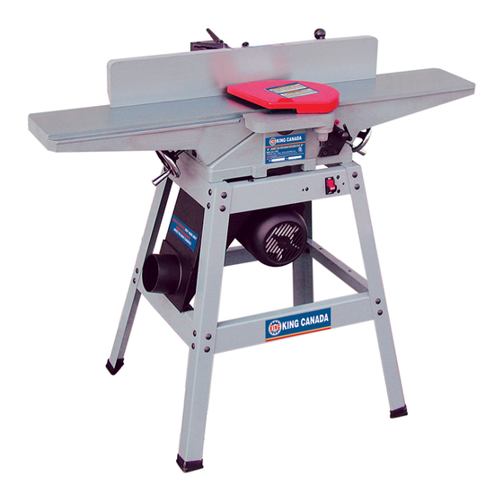
6” JOINTER MODEL: KC-150C INSTRUCTION MANUAL COPYRIGHT © 2001 ALL RIGHTS RESERVED BY KING CANADA TOOLS INC. -
Page 2: Replacement Parts
Warranty does not apply to defects due directly or indirectly to misuse, abuse, negligence or accidents, repairs or alterations and lack of maintenance. KING CANADA shall in no event be liable for death, injuries to persons or property or for incidental, special or consequential damages arising from the use of our products. -
Page 3: General Safety Instructions For Power Tools
GENERAL SAFETY INSTRUCTIONS FOR POWER TOOLS 1. KNOW YOUR TOOL 12. ALWAYS WEAR SAFETY GLASSES. Read and understand the owners manual and labels affixed to Always wear safety glasses (ANSI Z87.1). Everyday the tool. Learn its application and limitations as well as its eyeglasses only have impact resistant lenses, thet are NOT specific potential hazards. -
Page 4: Additional Safety Instructions
ADDITIONAL SAFETY INSTRUCTIONS FOR YOUR JOINTER READ AND UNDERSTAND INSTRUCTION MANUAL 7. CLEARING THE TABLE OF ALL OBJETS. BEFORE OPERATING JOINTER Never turn your jointer on before clearing the table of all objects 1. DO NOT ALTER OR MISUSE THE TOOL. (tools, scraps of wood...) except for the workpiece and related These tools are precision built. -
Page 5: Assembling Stand
6” JOINTER ASSEMBLY ASSEMBLY INSTRUCTIONS WARNING: FOR YOUR OWN SAFETY, DO NOT CONNECT THE JOINTER TO THE POWER SOURCE UNTIL THE JOINTER IS COMPLETELY ASSEMBLED AND YOU HAVE READ AND UNDERSTOOD THE ENTIRE OWNER’S MANUAL. ASSEMBLING STAND 1. Assemble two 11-3/4˝ long top end braces (A) Fig. 1, two 15-3/4˝ long top side braces (B), two 16-1/2 long lower end braces (C), and two 20-1/2˝... -
Page 6: Assembling Jointer To Stand
6” JOINTER ASSEMBLY ASSEMBLING JOINTER TO STAND 1. WARNING: JOINTER WEIGHT IS APPROXIMATELY 175 LBS. CARE MUST BE TAKEN WHEN LIFTING JOINTER ONTO STAND. A MINIMUM OF TWO PEOPLE WILL BE REQUIRED TO LIFT THE MACHINE. 2. The infeed end of the jointer is fastened to the two holes (A) Fig. 5, and the outfeed end of the jointer is fastened to hole (B) on the top end FIGURE 5 braces. - Page 7 6” JOINTER ASSEMBLY ASSEMBLING MOTOR PULLEY 1. Assemble motor pulley (A) Fig. 12, to motor shaft with the hub of the pulley in the outer position as shown. Make sure key (B) is inserted in the keyway of the motor pulley and shaft. ASSEMBLING BELT, ALIGNING PULLEYS, AND ADJUSTING BELT TENSION 1.
-
Page 8: Assembling Fence
6” JOINTER ASSEMBLY ASSEMBLING FENCE 1. Insert hexagon rod (A) Fig. 16, of fence assembly into bracket (B) on jointer as shown. NOTE: If fence does not slide in and out easily, loosen two screws (X) Fig. 16, and adjust bracket (B). Then tighten two screws (X). 2. -
Page 9: Electrical Requirements
LINE CHANGING VOLTAGE 220V The motor supplied with your King Canada 6˝ jointer is a dual FIGURE 22 voltage, 110/220V, single phase motor which is wired for 110V operation. If you desire to operate the machine at 220V, the following... -
Page 10: Locking Switch In The "Off" Position
OPERATING CONTROLS AND ADJUSTMENTS 6” JOINTER STARTING AND STOPPING JOINTER The On/Off switch (A) Fig. 24, is located on the top side brace of the stand. To turn the machine “ON”, move the switch (A) to the up position. To turn the machine “OFF”, move the switch (A) to the down position. - Page 11 OPERATING CONTROLS AND ADJUSTMENTS 6” JOINTER INFEED TABLE POSITIVE STOPS 1. Positive stops are provided to limit the height and depth of the infeed table. To adjust the stops, simply loosen two lock nuts (F) and (G) Fig. 28, and turn the two adjusting screws (J) and (K) as required. Then retighten the lock nuts (F) and (G).
-
Page 12: Adjusting Table Gibs
OPERATING CONTROLS AND ADJUSTMENTS 6” JOINTER 7. If the knives are set too low, the result will be as shown in Fig. 34, and the finished surface will be curved. Work Outfeed Infeed table table Cutter Knives set too low 8. -
Page 13: Fence Operation
OPERATING CONTROLS AND ADJUSTMENTS 6” JOINTER FENCE OPERATION The fence can be moved across the table and can tilt 45 right or left at any position on the table a follows: 1. To move the fence across the table, loosen lock handle (A) Fig. 39, slide fence to the desired position on the table and tighten lock handle (A). -
Page 14: Adjusting Fence
OPERATING CONTROLS AND ADJUSTMENTS 6” JOINTER 8. Loosen lock handle (C) Fig. 44, and tilt fence inward as far as possible, as shown, and tighten lock handle (C). 9. Using a square (D) Fig. 44 check to see if the fence is at a 45 inward angle to the table, as shown. -
Page 15: Removing, Replacing And Resetting Knives
OPERATING CONTROLS AND ADJUSTMENTS 6” JOINTER REMOVING, REPLACING AND RESETTING KNIVES If the knives are removed from the cutterhead for replacement or regrinding, care must be used in removing, replacing and resetting them as follows: 1. DISCONNECT THE MACHINE FROM ITS POWER SOURCE. 2.
Need help?
Do you have a question about the KC-150C and is the answer not in the manual?
Questions and answers