
Related Manuals for King Canada KC-110C


Summary of Contents for King Canada KC-110C
-
Page 1: Instruction Manual
KING CANADA 10” DRILL PRESS MODEL: KC-110C INSTRUCTION MANUAL COPYRIGHT ® 2002 ALL RIGHTS RESERVED BY KING CANADA TOOLS INC. -
Page 2: Limited Warranty
Warranty does not apply to defects due directly or indirectly to misuse, abuse, negligence or accidents, repairs or alterations and lack of maintenance. KING CANADA shall in no event be liable for death, injuries to persons or property or for incidental, special or consequential damages arising from the use of our products. -
Page 3: General Safety Instructions For Power Tools
GENERAL SAFETY INSTRUCTIONS FOR POWER TOOLS 1. KNOW YOUR TOOL 12. ALWAYS WEAR SAFETY GLASSES. Read and understand the owners manual and labels affixed to Always wear safety glasses (ANSI Z87.1). Everyday the tool. Learn its application and limitations as well as its eyeglasses only have impact resistant lenses, thet are NOT specific potential hazards. -
Page 4: Specifications
SPECIFICATIONS VOLTAGE ..........................................120V AMPS ............................................3.2A MOTOR R.P.M........................................1700 Hz ..............................................60 PHASE ............................................1 CHUCK CAPACITY ......................................1/2” DISTANCE BETWEEN SPINDLE AXIS AND COLUMN ..........................5” MAX. SPINDLE TRAVEL ....................................2-3/8” MAX. DISTANCE FROM CHUCK TO THE TABLE..........................9-3/4” MAX. DISTANCE FROM CHUCK TO THE BASE ..........................14-1/4” RANGE OF SPINDLE SPEEDS (1700 MOTOR R.P.M AT 60Hz) ..............570, 900, 1390, 2050, 3050 R.P.M. -
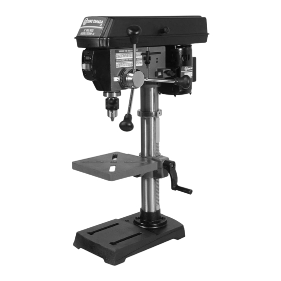
Page 5: Getting To Know Your Drill Press
GETTING TO KNOW YOUR DRILL PRESS FIGURE 1 LOCATION AND FUNCTION OF CONTROLS 1. BELT TENSION LOCK HANDLE...Tightening handles locks the others. Just above it you will find the light switch to illuminate motor bracket support to maintain the correct belt distance and the work table during operations. - Page 6 UNPACKING/TOOLS NEEDED Your Drill Press is shippec complete in one box. Separate all loose parts and compare with illustrations on this page to make sure all parts are accounted for. Remove protective oil that is applied to the table and column.
-
Page 7: Electrical Connections
WARNING: TO MAINTAIN PROPER GROUNDING OF YOUR DRILL PRESS, DO NOT REMOVE OR ALTER THE GROUNDING 120V WIRING DIAGRAM MODEL:KC-110C PRONG IN ANY MANNER. GREEN 120V OPERATION... -
Page 8: Assembly Instructions
ASSEMBLY INSTRUCTIONS Rack BASE, COLUMN & TABLE ASSEMBLY Column 1. Position the base on the floor. Remove the protective covering and Base discard. 2. Remove protective sleeve from the column and discard. Place the column assembly on the base, align the holes in the column support with the holes in the base. - Page 9 ASSEMBLY INSTRUCTIONS Rack 8. While holding the rack and table support in an engaged position, Column slide both down over the column. Slide rack down the column until Table Support the rack is positioned against the lower column support. Fig.10. Lower Column 9.
- Page 10 ASSEMBLY INSTALLING THE CHUCK FIG.14 Chuck Spindle Nose Sleeve 1. Locate the chuck in the box of parts. 2. Clean out the tapered hole in the chuck, also clean the spindle nose with a clean cloth. Make sure there are no foreign particles sticking to the surfaces. The slightest piece of dirt on the spindle nose or the chuck will prevent the chuck from seating properly.
-
Page 11: Operating & Adjustments
OPERATING & ADJUSTMENTS INSTALLING DRILL BITS FIG.18 Chuck Key Insert the drill bit into the chuck far enough to obtain the maximum gripping of the chuck jaws. The chuck jaws are approximately 1” long. When using a small drill bit, do not insert it so far that the jaws touch the Chuck flutes (spiral grooves) of the bit. -
Page 12: Maintenance & Troubleshooting
It falls off when trying tapered surface. dirt, grease and oil. to install it. PARTS DIAGRAM & PARTS LISTS Refer to the Parts section of the King Canada web site for the most updated parts diagram and parts list. - Page 13 INSTRUCTIONS FOR DUAL LASER GUIDE SYSTEM USING/ADJUSTING DUAL LASER GUIDE SYSTEM WARNING! Do not look directly at the laser beams. Do not aim the laser beams at any person or any object other than your workpiece. Do not deliberately aim the beams into the eye of a person for any length of time. Do not use the laser guide system aimed at a reflective workpiece, wood or rough coated surfaces are acceptable.
- Page 14 Service Manual / Manuel de Service 10” Drill Press with Dual Laser Guide System Perceuse À Colonne 10” avec Guide de Laser Double Revised/Revisé 08/2008 KC-110C Downloaded from www.Manualslib.com manuals search engine...
- Page 15 KC-110C Parts Pricing List / Liste de Prix des Pièces Description Française Price/Prix Diag. Order # Com. English Description Qty./Qté. 4001100010 COLUMN COLONNE $34.33 CREMAILLIERE $22.60 4001100020 RACK SUPPORT DE LA COLONNE $16.73 4001100030 COLUMN SUPPORT BASE $44.45 4001100040 BASE BOULON HEXAGONAL $1.78...
- Page 16 SET SCREW VIS SANS TETE $1.55 4001100950 LASER GUIDE GUIDE AU LASER $17.08 400110MBIL BILINGUAL MANUAL KC-110C MANUEL BILINGUE KC-110C $15.00 Pricing subject to change without prior notice. / Prix sujet à changement sans préavis. Downloaded from www.Manualslib.com manuals search engine...
Need help?
Do you have a question about the KC-110C and is the answer not in the manual?
Questions and answers