Advertisement
Available languages
Available languages
Quick Links
Montageanleitung
Assembly Instructions
Die abgebildeten Zeichnungen
des Produkts dienen nur als
Referenz und können vom tat-
sächlichen Produkt abweichen.
The product drawings shown are
for reference only and may differ
from the actual product.
BS Bodensteckdosen Systemtechnik GmbH | Dingerdisser Str. 36, 33699 Bielefeld
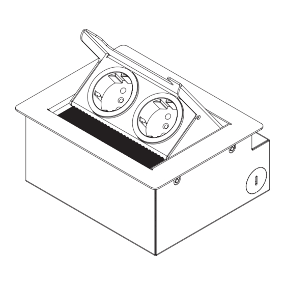
32er E-Serie
32 E-Series
3202E, 3203E
Advertisement

Related Manuals for Bodensteckdosen Systemtechnik 32E Series


Summary of Contents for Bodensteckdosen Systemtechnik 32E Series
- Page 1 Produkts dienen nur als Referenz und können vom tat- 32 E-Series sächlichen Produkt abweichen. The product drawings shown are 3202E, 3203E for reference only and may differ from the actual product. BS Bodensteckdosen Systemtechnik GmbH | Dingerdisser Str. 36, 33699 Bielefeld...
-
Page 2: Table Of Contents
Inhalt/Contents Produktbeschreibung...........U 3 Technische Daten ..........U 4 Montageanleitung Hohlboden ......1 Montageanleitung Tisch/Arbeitsplatte ..... 8 Montageanleitung Estrichboden ....... 12 Gebrauchshinweise ..........U 5 Product description ..........U 3 Technical data ............U 4 Installation in raised access floor ...... 19 Installation in a table/countertop ...... 26 Installation in screed floor ........ - Page 3 32er E-Serie/ 32 E-Series Exemplarisch ist die Bodensteckdose 3202E The floor socket 3202E is shown as an example. abgebildet. Das Montageprinzip gilt auch für The assembly principle also applies to the floor die Bodensteckdose 3203E. socket 3203E. Bezeichnung/Designation: Geräteträger/Device carrier ...
-
Page 4: Technische Daten
Technische Daten/Technical specifications Art.-Nr. 3202E 3203E Einbaumaße 167 x 124 mm 225 x 123 mm Hohlboden Einbaumaße 166 x 82 x 146 mm 224 x 82 x 144 mm Estrich 2 x seitlich, 2 x hinten, 2 x seitlich, 2 x hinten, Zuleitungen 2 x unten, je Ø... - Page 5 Montage im Hohlboden Schritt 1 Den Geräteträger vom Rahmen abmontieren.
- Page 6 Schritt 2 Die Bügel zusammen mit dem Rahmen und dem Rahmenträger von der Box abschrauben. Die Box wird für den Einbau im Hohlboden nicht mehr benötigt.
- Page 7 Schritt 3 Danach den Rahmen vom Rahmenträger abschrauben. (Ansicht von unten)
- Page 8 Schritt 4 Hiernach die Bügel vom Rahmenträger Die Bügel werden für den Einbau im demontieren. Anschließend den Rahmen Hohlboden nicht mehr benötigt. wieder an den Rahmenträger anschrauben.
- Page 9 Schritt 5 An gewünschter Position einen Ausschnitt den Hohlboden (H) sägen/schneiden. Die in der Größe der Einbaumaße für Leehrohre/Leitungen (L) zu dieser Position Hohlböden (siehe Tabelle Seite U4) in verlegen. den Bodenbelag (B) (falls vorhanden) und...
- Page 10 Schritt 6 Falls noch nicht vorhanden, den Boden- Bodenbelag (B) verteilen. Nun die Rahmen- gruppe (Rahmen + Rahmenträger ) belag (B) verlegen. Anschließend einen Konstruktionskleber (K) (z. B. „beko ALLCON in den Ausschnitt absenken und auf den 10“) rund um den Ausschnitt auf dem Bodenbelag (B) absetzen.
- Page 11 Schritt 7 Die Geräte anschließen, danach den Geräteträger in den Rahmen einschrauben. Fertig!
- Page 12 Montage im Tisch/Arbeitsplatte Schritt 1 Schritt 2 Demontage des Geräteträgers , An gewünschter Position einen Ausschnitt Rahmens , Rahmenträgers , Bügels in der Größe der Einbaumaße für von der Box – siehe Schritte 1–4 für den Hohlböden (siehe Tabelle Seite U4) in die Einbau im Hohlboden (Seite 1–4)! Tischplatte (TP) sägen/schneiden.
- Page 13 Schritt 3 Danach den Rahmenträger in der Der Versatz ( ) zwischen der Oberkante des Rahmenträgers und der Tischoberfläche Tischplatte (TP) verschrauben. WICHTIG! Den Rahmenträger mit einem sollte dabei zwischen 1–3 mm gewählt Versatz ( ) zur Tischoberfläche befestigen. werden.
- Page 14 Schritt 4 Anschließend den Rahmen wieder am Rahmenträger montieren.
- Page 15 Schritt 5 Zuletzt die Geräte anschließen, danach den Geräteträger in den Rahmen einschrauben. Fertig!
- Page 16 Montage im Estrich Schritt 1 Den Geräteträger vom Rahmen abmontieren.
- Page 17 Schritt 2 Anschließend die Schrauben am Bügel lösen und die Rahmengruppe (Rahmen + Rahmenträger ) mit den Bügeln aus der Box nehmen.
- Page 18 Schritt 3 Vor dem Gießen des Estrichs einen Polystyrol-Block (PB), der in seiner äußeren Abmessung umlaufend ca. 40 mm größer ist als die Box *, als Platzhalter auf die ausgelegte Dämmschicht (P) kleben. Danach die Leerrohre (L) verlegen und senkrecht am Polystyrol-Block (PB) befestigen.
- Page 19 Schritt 4 Die Box beim Absatz/Sockel mit selbstklebendem Dichtungsband (DB) (z. B. Moosgummi) abdichten. Einen Randdämmstreifen (RS) (Estrich- dämmstreifen) umlaufend an der Box befestigen und am Absatz/ Sockel vorsichtig einschneiden.
- Page 20 Schritt 5 Nach dem Gießen des Estrichs den Polystyrol-Block (PB) aus dem Estrich entfernen. Danach die Box in die ent- standene Bodenaussparung auf Mörtelbett* (M) einsetzen und die Leerrohre (L) seitlich in die Öffnungen der Box einführen. *Achtung! Die Höhe des Mörtelbetts (M) muss so ...
- Page 21 Schritt 6 Die Box abdichten. (Empfehlung: das Gehäuse oben abdecken, oder abkleben, wie abgebildet). Die Aussparung um die Box nun mit Mörtel (M) auffüllen. Die Position der Box vor dem Aushärten des Mörtels (M) mit der Wasserwaage (W) überprüfen!
- Page 22 Schritt 7 Zuletzt die Geräte anschließen und den Nach dem Aushärten des Mörtels (M) Geräteträger wieder in den Rahmen den Belag (B) im Raum verlegen. Danach die Rahmengruppe (Rahmen + einschrauben. Die Bodensteckdose Rahmenträger ) mit den Bügeln ist nun erfolgreich eingebaut.
-
Page 23: Installation In Raised Access Floor
Installation in the raised access floor Step 1 Unscrew the device carrier from the frame . - Page 24 Step 2 Unscrew the brackets together with the frame and the frame carrier from the box . The Box is no longer required for installation in the cavity floor.
- Page 25 Step 3 Then unscrew the frame from the frame carrier . (bottom view)
- Page 26 Step 4 Remove the brackets from the frame The brackets are no longer required for carrier . Then screw the frame back onto installation in raised access floors/cavity the frame carrier . floors.
- Page 27 Step 5 At the desired position, saw/cut a cut-out the flooring (B) (if present) and the cavity in the size of the installation dimensions floor (H). Route the conduits/lines (L) to this for cavity floors (see table on page U4) in position.
- Page 28 Step 6 If not already present, lay the flooring (B). on the flooring (B). Now lower the frame module (frame + frame support ) into Then spread a construction adhesive (K) (e.g. „beko ALLCON 10“) around the cut-out the cutout and place it on the flooring (B).
- Page 29 Step 7 Connect the devices, then screw the device carrier into the frame . Finished!
-
Page 30: Installation In A Table/Countertop
Installation in a table/countertop Step 1 Step 2 Disassembly of the device carrier , At the desired position, saw/cut a section frame , frame carrier , bracket from in the size of the installation dimensions the box – see steps 1–4 for installation in for raised access floor (see table on page the raised floor (page 19–22)! U4) in the table top (TP). - Page 31 Step 3 Screw the frame carrier into the The offset ( ) between the upper edge of the frame carrier and the table surface table top (TP). IMPORTANT! Fasten the frame carrier should be between 1–3 mm. with an offset ( ) to the table surface.
- Page 32 Step 4 Then mount the frame back on the frame carrier .
- Page 33 Step 5 Finally, connect the devices, then screw the device carrier into the frame . Complete!
-
Page 34: Installation In Screed Floor
Installation in the screed floor Step 1 Unscrew the device carrier from the frame . - Page 35 Step 2 Then loosen the screws on the bracket and take the frame module (frame + frame carrier ) with the brackets out of the box .
- Page 36 Step 3 Before pouring the screed, a polystyrene block (PB) with a circumference of approx. 40 mm larger than the box in its outer dimension* must be glued to the insulation layer (P) as a placeholder. Then lay the conduits (L) and fix them (e.
- Page 37 Step 4 Seal the box at the step/plinth with self-adhesive sealing tape (DB) (e.g. foam rubber). Fasten an insulation strip (RS) (screed insulation strip) around the box and carefully cut into it at the position of the step/plinth.
- Page 38 Step 5 Remove the polystyrene block (PB) after pouring the screed. Now insert the box into the resulting floor recess on a mortar bed* and install the conduits into the openings of the box . *Attention! The height of the mortar bed (M) must ...
- Page 39 Step 6 Seal the box opening (Tip: cover the box opening, as shown.) Now fill the recess around the box with mortar (M). Check the position of the box with the spirit level (W) before curing the mortar!
- Page 40 Step 7 and screw the device carrier back After curing, lay the flooring (B) in the room. into the frame . The floor socket is now Then mount the frame module (frame + frame carrier ) with the brackets back successfully installed.
-
Page 41: Instructions For Use
Gebrauchshinweise/Instructions for use Um eine anhaltende Funktion der Bodensteckdose In order to ensure a lasting function of the zu gewährleisten sind folgende Hinweise zu floor socket, the following instructions must beachten: be observed: • Anschluss, Reparatur oder Instandhaltung sind • Connection, repair or maintenance must be carried von einer ausgebildeten Fachkraft durchzuführen. - Page 42 © by BS Bodensteckdosen Systemtechnik GmbH BS Bodensteckdosen Systemtechnik GmbH Dingerdisser Str. 36 33699 Bielefeld Tel +49 521 9892780 Fax +49 521 989278-30 info@bodensteckdosen.com www.bodensteckdosen.com Irrtümer und technische Änderungen vorbehalten. Subject to errors and technical changes.
Need help?
Do you have a question about the 32E Series and is the answer not in the manual?
Questions and answers