Advertisement
Available languages
Available languages
Quick Links
Advertisement

Related Manuals for Bodensteckdosen Systemtechnik 76 A-Series


Summary of Contents for Bodensteckdosen Systemtechnik 76 A-Series
- Page 1 Bedienungsanleitung Instruction Manual 76er A-Serie 76 A-Series...
-
Page 2: Table Of Contents
Inhalt/Contents Technische Daten ����������������������������������� 3 Produktbeschreibung ���������������������������� 4 Montageanleitung ����������������������������������� 5 Gebrauchshinweise ������������������������������ 21 Technical specifications 3 Product description 4 Assembly instructions 13 Instructions for use 21... -
Page 3: Technische Daten
Technische Daten/Technical specifications Art.-Nr. 7601A 7602A 7604A Einbaumaße 100 x 100 x 82 mm 200 x 100 x 82 mm 200 x 200 x 82 mm Zuleitungen 2 x seitlich, M25 x 1,5 4 x seitlich, M25 x 1,5 4 x seitlich, M25 x 1,5 Nivellierbar –... -
Page 4: Produktbeschreibung
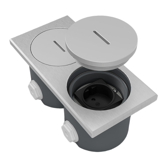
The 7602A floor socket is shown as an abgebildet. Das Montageprinzip gilt für alle example The installation principle applies Bodensteckdosen der 76er A-Serie: 7601A, to all floor sockets from the 76 A-Series: 7602A, 7604A. 7601A, 7602A, 7604A Bezeichnung/Designation: Deckel/Lid ... -
Page 5: Montageanleitung
Montageanleitung Schritt 1 Schritt 2 (Vorbereitungen) Den Deckel entnehmen und den Vor dem Pflastern die Einbauposition Geräteträger von dem Gehäuse für die Bodensteckdose festlegen und die abmontieren� Anschließend die flexiblen Leitungen (L) im Splitt (SP) zu Kabelverschraubungen anbringen� dieser Position verlegen�... - Page 6 Schritt 3 Den Bodenbelag (B) (Pflastersteine) bis zur Einbauposition der Bodensteckdose verlegen und die Bodensteckdose als Platzhalter einsetzen� Alternativ einen Platzhalter aus Polystyrol in den Einbaumaßen der Bodensteckdose zuschneiden�...
- Page 7 Schritt 4 Anschließend die Plastersteinreihe zu Ende verlegen, die Bodensteckdose/ den Platzhalter entnehmen und ein Mörtelbett (M) an der Einbauposition, auf den verdichteten Untergrund (K) (z. B. Kies) gießen�...
- Page 8 Schritt 5 Hiernach die flexiblen Leitungen (L) durch die Kabelverschraubungen in das Gehäuse einführen und die Bodensteckdose in das Mörtelbett (M) einsetzen�...
- Page 9 Schritt 6 Die Position der Bodensteckdose vor dem Aushärten des Mörtels (M) mit der Wasserwaage (W) überprüfen� Achtung: Die Höhe des Mörtelbetts (M) muss so vermessen werden, dass die Bodensteckdose und der Belag (B) bündig sind (fluchtend sind)!
- Page 10 Schritt 7 Nach dem Aushärten des Mörtels (M) die Steckdosen anschließen und den Geräte- träger in das Gehäuse montieren� Danach Aussparungen für die flexiblen Leitungen (L) und für die Kabelverschrau- bungen in die Steine schneiden (siehe Abb. unten und Gegenansicht rechts), so dass diese plan an die Bodensteckdose gelegt werden können, ohne die Leitungen zu beschädigen�...
- Page 11 Ansicht von der Gegenseite.
- Page 12 Schritt 8 Mit dem Pflastern fortfahren� Die Boden- steckdose ist nun erfolgreich eingebaut�...
-
Page 13: Assembly Instructions
Assembly Instructions Step 1 Step 2 (Preparations) Remove the lid and dismantle the device Before paving, determine the installation carrier from the housing � Then attach position for the floor socket and lay the the cable glands � flexible cables (L) in the gravel (SP) to this position�... - Page 14 Step 3 Lay the floor covering (B) (paving stones) up to the installation position of the floor socket and use the floor socket as a place- holder� Alternatively, cut a polystyrene placeholder in the size of the installation dimensions of the floor socket�...
- Page 15 Step 4 Then lay the row of paving stones to the end, remove the floor socket/the place- holder and pour a bed of mortar (M) at the installation position on the compacted subsurface (K) (e. g. gravel).
- Page 16 Step 5 Then insert the flexible cables (L) through the cable glands into the housing and insert the floor socket into the mortar bed (M)�...
- Page 17 Step 6 Before the mortar (M) hardens, check the position of the floor socket with the spirit level (W)� Attention: The height of the mortar bed (M) must be measured so that the floor socket and the covering (B) are flush (are in alignment)!
- Page 18 Step 7 After the mortar (M) has hardened, connect the sockets and mount the device carrier in the housing � Then cut the recesses for the flexible cables (L) and for the cable glands in the stones so that they can be laid flat on the floor socket without damaging the cables (see figure below and opposite view on the right)�...
- Page 19 View from the opposite side.
- Page 20 Step 8 Continue paving� The floor socket is now successfully installed�...
-
Page 21: Gebrauchshinweise
Gebrauchshinweise/Instructions for use Um eine anhaltende Funktion der Bodensteckdose zu In order to ensure a lasting function of the floor socket, gewährleisten sind folgende Hinweise zu beachten: the following instructions must be observed: • Anschluss, Reparatur oder Instandhaltung sind von •... - Page 22 © by BS Bodensteckdosen Systemtechnik GmbH BS Bodensteckdosen Systemtechnik GmbH Dingerdisser Str� 36 33699 Bielefeld Tel +49 521 9892780 Fax +49 521 989278-30 info@bodensteckdosen�com www�bodensteckdosen�com Irrtümer und technische Änderungen vorbehalten. Subject to errors and technical changes.
Need help?
Do you have a question about the 76 A-Series and is the answer not in the manual?
Questions and answers