Advertisement
Available languages
Available languages
Quick Links
Advertisement

Related Manuals for Bodensteckdosen Systemtechnik 8902B


Summary of Contents for Bodensteckdosen Systemtechnik 8902B
- Page 1 Bedienungsanleitung Instruction Manual 8902B...
- Page 2 Inhalt/Contents Technische Daten und Gebrauchshinweise ....3 Produktbeschreibung ............4 Montageanleitung ..............5 Product description .............. 4 Technical data and instructions for use .......12 Assembly instructions ............13...
-
Page 3: Technische Daten
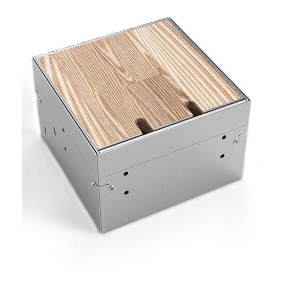
Einbaumaße Zuleitungen Nivellierbar Schutzart Belastbarkeit 155 x 157 x 2 x seitlich, 2 x hinten, Flächenlast 8902B 30 mm IP20 90–120 mm 2 x unten, Ø 25 mm max. 120 kg Gebrauchshinweise Um eine anhaltende Funktion der Bodensteckdose • Pflegehinweis: Das Produkt ist für die Trocken- zu gewährleisten sind folgende Hinweise zu... - Page 4 8902B Bezeichnung/Designation: Deckel/Lid Rahmen/Frame Nivellierschrauben/Leveling screw Geräteträger/Device carrier Box/Box...
- Page 5 Montageanleitung Schritt 1 Schritt 2 Den Deckel abnehmen und den Eine Styrodurplatte (SP) auf das Fundament (F) Geräteträger von der Box abmontieren. kleben. Anschließend die Box auf die Styrodurplatte (SP) kleben (oder mit Schrauben (M4) im Fundament) verdübeln. Danach die Leerrohre (L) an die Box ...
- Page 6 Schritt 3 Einen Randdämmstreifen (RS) (Estrichdämmstreifen) umlaufend an der Box befestigen. Die obere Öffnung der Box mit einem Pappdeckel (PD) oder Styrodur abdecken.
- Page 7 Schritt 4 Auf dem Boden eine Dämmschicht (Polystyrol) (P) verlegen. Anschließend den Estrich (E) gießen. Nachdem der Estrich (E) getrocknet ist, die Abdeckung (PD) von der Box entfernen.
- Page 8 Schritt 5 Die Geräte anschließen und den Geräteträger in die Box einschrauben. Den Bodenbelag (B) im Raum verlegen und den Deckel mit Belag (B) auskleben. Umlaufend um die Dose, Platz für eine Flexfuge (FF) frei lassen. Mithilfe der Nivellier- schrauben ...
- Page 9 Schritt 6 Flexfuge (FF) aus Silikon oder Kork einsetzen. Schließlich den Deckel wieder in den Rahmen installieren. Die Bodensteckdose ist nun erfolgreich eingebaut. (Siehe Querschnitt unten).
- Page 10 Achtung! Sollte die Höhe des Bodenbelags (B) niedriger ausfallen als die Höhe der Bodensteckdose (unter 100 mm), können die perforierten Laschen (G) an der oberen Boxkante heraus- gebrochen werden.
- Page 11 Ansicht im Querschnitt mit herausgebrochenen Laschen. (B) Bodenbelag, (E) Estrich, (F) Fundament, (FF) Flexfuge, (P) Polystyrol-Dämmschicht.
-
Page 12: Technical Specifications
Supply Levellable Protection Load 153 x 157 x 2 x lateral, 2 x back, Area load 8902B 30 mm IP20 90–120 mm 2 x bottom, Ø 25 mm max. 120 kg Instructions for use In order to ensure a lasting function of the •... - Page 13 Assembly Instructions Step 1 Step 2 Remove the lid . Then remove the device Glue a Styrodur plate (SP) to the foundation (F). carrier from the box . Then glue the box onto the Styrodur plate (SP) (or dowel with screws (M4) in the foundation).
- Page 14 Step 3 Fasten an insulation strip (RS) (screed insulation strip) around the box . Cover the upper opening of the box with a cardboard lid (PD) or Styrodur.
- Page 15 Step 4 Lay an insulation layer (polystyrene) (P) on the floor. Then pour the screed (E). After the screed (E) has dried, remove the cover (PD) from the box .
- Page 16 Step 5 Connect the sockets and screw the device carrier into box . Lay the floor covering (B) in the room and glue the covering (B) into the lid . Leave space for a flex joint (FF) all around the floor socket.
- Page 17 Step 6 Insert flexible joint (FF) made of silicone or cork. Finally, place the lid into the frame again. The ground socket is now successfully installed. (See cross section below.)
- Page 18 Attention! If the height of the floor covering (B) is lower than the height of the floor socket (less than 100 mm), the per- forated tabs (G) on the upper edge of the box can be broken out.
- Page 19 Cross-sectional view with tabs broken out. (B) floor covering, (E) screed, (F) foundation, (FF) flexible joint, (P) polystyrene insulation layer.
- Page 20 Irrtümer und technische Änderungen vorbehalten. Errors and technical changes reserved. BS Bodensteckdosen Systemtechnik GmbH Dingerdisser Str. 36 | 33699 Bielefeld | Tel +49 521 9892780 info@bodensteckdosen.com | www.bodensteckdosen.com...
Need help?
Do you have a question about the 8902B and is the answer not in the manual?
Questions and answers