Intermatic IG1240RC - Surge Protector Installation
- Installation instructions (2 pages)
Advertisement
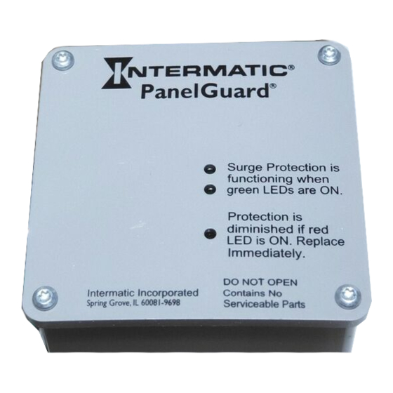
DEVICE APPEARANCE

CAUTION
Electricity is dangerous; follow safety rules. Never work on equipment with the electricity turned "ON". Be absolutely certain the power is turned "OFF" to the circuit or device you are installing. Be sure you read and understand all of these installation steps before you begin to install this Surge Protection Device. For your protection, check and follow your local electrical codes. Do not touch electric circuits or devices when you are wet or standing on a wet surface. Use a circuit tester or AC voltmeter to be sure the electricity is "OFF" before you touch wires or devices. This device is suitable for use on a circuit capable of delivering not more than 25,000 rms symmetrical ampers, 240 volts maximum.
NOTE:
ELECTRICAL GROUND IS REQUIRED FOR THIS UNIT TO FUNCTION PROPERLY AND SAFELY!
INSTALLATION
- Select a mounting location for the Surge Protection Device (SPD) which will allow convenient connection to the panel while keeping the lead wires as short as possible. Use an AC voltmeter or circuit tester across two breaker outputs to confirm that there is 240 volts between them. If the voltage is 0, select a different breaker of equal amperage.
- Check all parts to be sure none are missing. You should have:
| QUANTITY | DESCRIPTION |
| 1 | IG1240RC Panel Protector with a threaded connector and locking nut. |
| 1 | Conduit Nut |
- Select the mounting for the protector at the panel. If you have a panel that is not like the diagram (Fig. 3) call (815) 675-7000 for assistance between 8:00 am and 4:00 pm, weekdays, central time.
- If you do not have a main power shut "OFF" (master switch) do not attempt the work. Call a licensed electrician. Turn the main breaker or shut off switch to the "OFF position). Use the circuit tester or AC voltmeter to be sure the circuits are off.
- Carefully remove the front trim panel. Choose and remove the desired knockout through which the Protector wiring will enter into the breaker panel. Try to select a knockout that will allow you to use the shortest possible length of wire between the protector and the circuit breakers.
- Install the Protector by inserting the wire and the threaded connector into the hole you knockedout in the breaker panel and secure it with the locknut provided. If the breaker panel is recess mounted into the wall use the IG12FMP-3
Flush Mounting Kit to recess the Protector. Follow the instructions packaged with the flush mounting kit. - Check to assure that the electricity is "OFF". A neon circuit tester or AC Voltmeter can be used, if you have one.
When connecting the wires, the green (ground) wire is connected first, then the white (neutral) wire and the black wires as shown below. The black wires should be connected next to each other to two 15 or 20 ampere circuit breakers.
![]()

A=Black (Line, right half)
B=Black (Line, left half)
C=White (Neutral)
D=Green (Ground)
NOTE: The protector functions best if all bends in the wires are rounded, ideally to a 4" radius. Hard 90˚ bends reduce efficiency. Cut all leads to correct length.
DO NOT COIL EXCESS LEAD. - Route the green wire to the ground bus bar provided in the breaker panel. Some panels do not have a separate ground bus bar so the green wire must then be connected to the neutral bus bar mentioned in Step 9. This wire must be connected for safety purposes.
- Next, route and connect the white wire to the neutral bus bar provided in the breaker panel.
- The two black wires remaining must be connected to two separate 15 or 20 amp circuit breakers, not to each other, to insure connection across the full 240 volt AC incoming power circuit. Use the AC voltmeter or circuit tester across the black wire connection to be sure the protector is providing full protection to your panel. Not more than one wire should be connected to circuit breaker. It may be necessary to add new breakers.
- Check to be sure all wires are securely fastened and all screws are tight. You can confirm that the protector is wired to the correct breakers if you can read 220 to 240 volts AC between the two breakers that the protector is connected to. If there is no voltage between the two breakers, check to be sure that both of the breakers and the master breaker are "ON". If there is still no voltage between the two breakers, then they are probable on the same leg, and you will have to select another breaker for one of the black wires. BE SURE TO TURN OFF THE MAIN BREAKER BEFORE YOU ATTEMPT TO MOVE ANY WIRES.
Replace the front trim panel on the circuit breaker panel.


OPERATION
Both green indicator lights will be ON when power is present and the IG1240RC is operating properly. If one of the indicator lights is OFF, check the breakers to make sure that both are on and not tripped. If one or both of the green indicators are OFF, and the red indicator is on, the IG1240RC is no longer protecting. Replace the unit.
Documents / ResourcesDownload manual
Here you can download full pdf version of manual, it may contain additional safety instructions, warranty information, FCC rules, etc.
Advertisement


Need help?
Do you have a question about the IG1240RC and is the answer not in the manual?
Questions and answers