Table of Contents
Advertisement
Available languages
Available languages
Quick Links
SUPER 3600
Scarica questo manuale sul tuo cellulare
Téléchargez ce manuel sur votre mobile
Download this manual on your mobile
Laden Sie dieses Handbuch auf Ihr Handy herunter
Descarga este manual en tu móvil
Operatore
Operateur
Operator
Torantrieb
Operador
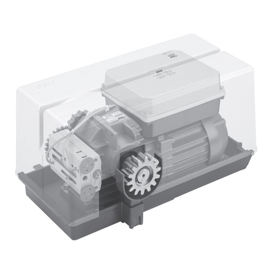
SUPER 3600
SUPER 3600 ICE
Die korrekte Bedienung des Bedieners ist nur gewährleistet, wenn er von einem RIB-Bedienpanel verwaltet wird
ITALIANO pag. 05 / FRANÇAIS pag. 17 / ENGLISH page 29/ DEUTSCH pag. 41 / ESPAÑOL pag. 53
Alimentazione
Peso max cancello
Alimentation
Poids maxi portail
Power Supply
Max gate weight
Stromspannung
Max Torgewicht
Alimentacion
Peso máx verja
230V 50/60 Hz
3600 kg
Il corretto funzionamento dell'operatore è garantito solo se viene gestito da un quadro di comando RIB
Le bon fonctionnement de l'opérateur n'est garanti que s'il est géré par un panneau de contrôle RIB
The correct operation of the operator is guaranteed only if it is managed by a RIB control panel
El funcionamiento correcto del operador solo está garantizado si está gestionado por un panel de control RIB
con / avec / with / mit
L1/R2-CRX
Disegni tecnici per progetti
Dessins techniques pour les projets
Technical drawings for projects
Technische Zeichnungen für Projekte
Dibujos técnicos para proyectos.
Manuali online interattivi
Manuels interactifs en ligne
Interactive online manuals
Interaktive Online-Handbücher
Manuales interactivos en línea.
Spinta max
Coppia max
Poussée maxi
Couple maxi
Max Thrust
Max torque
Max Schubkraft
Max. Drehmoment
Max Empuje
Coppia max
4700/4150 N
200/175 Nm
Vedere pagina 15
Voir page 27
See page 39
Siehe Seite 51
Ver página 63
Codice
Code
Code
Code
Codigo
AA31020
AA31024
Advertisement
Table of Contents

Subscribe to Our Youtube Channel
Related Manuals for Ribind SUPER 3600


Summary of Contents for Ribind SUPER 3600
- Page 1 3600 kg 4700/4150 N 200/175 Nm SUPER 3600 ICE AA31024 Il corretto funzionamento dell’operatore è garantito solo se viene gestito da un quadro di comando RIB Le bon fonctionnement de l’opérateur n’est garanti que s’il est géré par un panneau de contrôle RIB The correct operation of the operator is guaranteed only if it is managed by a RIB control panel Die korrekte Bedienung des Bedieners ist nur gewährleistet, wenn er von einem RIB-Bedienpanel verwaltet wird...
- Page 2 ISTRUZIONI DI SICUREZZA IMPORTANTI PER L’INSTALLAZIONE INSTRUCTIONS DE SECURITE IMPORTANTES POUR L’INSTALLATION ATTENZIONE - PER LA SICUREZZA DELLE PERSONE È IMPORTANTE CHE VENGANO SEGUITE TUTTE ATTENTION - POUR LA SECURITE DES PERSONNES, IL EST IMPORTANT DE SUIVRE TOUTES LES INSTRUCTIONS LE ISTRUZIONI CONSERVER SOIGNEUSEMENT CES INSTRUCTIONS CONSERVARE CON CURA QUESTE ISTRUZIONI...
- Page 3 IMPORTANT SAFETY INSTRUCTIONS FOR THE INSTALLATION WICHTIGE SICHERHEITS ANLEITUNGEN FÜR DIE INSTALLATIONEN ATTENTION - FOR THE SAFETY OF PEOPLE IT IS IMPORTANT TO FOLLOW ALL THE INSTRUCTIONS ACHTUNG - FÜR DIE SICHERHEIT DER PERSONEN IST ES WICHTIG, DASS ALLE ANWEISUNGEN KEEP THESE INSTRUCTIONS WITH CARE GENAU AUSGEFÜHRT WERDEN 1°...
- Page 4 ITALIANO RAEE - Informazione agli utilizzatori IMPORTANTES INSTRUCCIONES DE SEGURIDAD PARA LA Il simbolo del cassonetto barrato riportato sull’apparecchiatura o sulla sua confezione INSTALACIÓN indica che il prodotto alla fine della propria vita utile deve essere raccolto separatamente dagli altri rifiuti. L’utente dovrà, pertanto, conferire l’apparecchiatura giunta a fine vita agli idonei centri comunali di raccolta differenziata dei rifiuti elettrotecnici ed elettronici.
- Page 5 LAYOUT IMPIANTO A - Operatore SUPER 3600 B - Fotocellule esterne C - Cremagliera Modulo 6 D - Selettore a chiave E - Antenna radio F - Lampeggiatore H - Colonnina portafotocellula I - Fotocellula per protezione interna L - Costa meccanica...
- Page 6 INSTALLAZIONE SUPER 3600 CONTROLLO PRE-INSTALLAZIONE - IL CANCELLO DEVE MUOVERSI SENZA ATTRITI - N.B. È obbligatorio uniformare le caratteristiche del cancello alle norme e leggi vigenti. La porta può essere automatizzata solo se in buono stato e se rispondente alla norma EN 12604.
-
Page 7: Manutenzione
FISSAGGIO MOTORE E CREMAGLIERA La cremagliera va fissata a una certa altezza rispetto alla piastra di fissaggio del motore. Questa altezza può essere variata grazie a delle asole presenti sulla cremagliera. La registrazione in altezza viene fatta affinché il cancello durante il movimento, non si appoggi sull’ingranaggio di trazione del riduttore (Fig. -
Page 8: Collegamenti Elettrici
COLLEGAMENTI ELETTRICI L1 cod. AC08082 Manuali online interattivi Manuels interactifs en ligne Interactive online manuals Interaktive Online-Handbücher Manuales interactivos en línea. - Page 9 A - CONNESSIONI PROG È OBBLIGATORIO IMPOSTARE IL DIP 13 IN POSIZIONE ON. POWER 230 VAC MOTOR CAPACITOR L1 - N Alimentazione 230Vac 50/60Hz (120 Vac 60Hz a richiesta) PROBE NON DISPONIBILE Lampeggiatore (max 40 W) ENCODER NON DISPONIBILE Collegamento comune motore Terminazione RS485 di J11 Collegamento invertitori e condensatore motore APP+...
- Page 10 B - SETTAGGI START Comando impulso singolo (verde) CLOSE Comando Chiude (verde) OPEN Comando Apre (verde) DIP 1 (ON) - CONTROLLO PER MANUTENZIONE (PAG. 13) DIP 2 (ON) - PROGRAMMAZIONE TEMPI (PUNTO C) PROBE DIP 2-1 PROGRAMMAZIONE TEMPI APERTURA PEDONALE (PUNTO D) NON DISPONIBILE DIP 1-2 MEMORIZZAZIONE/CANCELLAZIONE CODICI RADIO COMANDO APERTURA TOTALE (DIP 1...
- Page 11 2 - Il led DL12 lampeggia rosso per 10 s. inserire nuovi codici come da procedure sopra descritte. 3 - Entro questi 10 s premere e mantenere premuto il pulsante PROG per 5 s.La cancellazione 4 - Riposizionare DIP 1, 2 e 3 su OFF. della memoria viene confermata da due lampeggi di color verde del led DL12 e da 2 toni del SEGNALAZIONE MEMORIA SATURA CODICI RADIO PER RELÉ...
-
Page 12: Caratteristiche Tecniche
le colonnine di supporto alle fotocellule al morsetto A - per proteggere le fotocellule da fonti Ha il compito di segnalare quando il cancello è aperto, parzialmente aperto o comunque non di disturbo. chiuso totalmente. Si spegne solo quando il cancello è completamente chiuso. Fate attenzione a non creare corto circuiti quando le fasi di alimentazione sono invertite! Durante l’apertura lampeggia lentamente. - Page 13 eseguire il ponticello fra COM A+ e EDGE 1/EDGE 2) DL13 blu acceso Alcune funzioni sono abilitate tramite smartphone, verificare quindi tramite smartphone lo stato della scheda in quanto lo stato dei dip/ trimmer potrebbe essere non veritiero. Sulla scheda esistono dei fusibili ripristinabili che intervengono in caso di corto circuito interrompendo l'uscita a loro assegnata.
- Page 14 DIFETTO SOLUZIONE Sulla scheda esistono dei fusibili ripristinabili che intervengono in caso di corto circuito interrompendo l'uscita a loro assegnata. A fronte di una ricerca guasti si consiglia di scollegare tutti i connettori estraibili e di inserirli uno a Dopo aver effettuato i vari collegamenti e aver dato tensione, tutti i led sono spenti. volta in modo da identificare più...
- Page 15 APP8054 Scheda APP+ APP8050 Scheda APP per gestire la centrale di comando per gestire la centrale di comando tramite Bluetooth tramite Bluetooth APP8064 Modulo Wi-Fi per Scheda APP8066 Modulo RJ45 per Scheda APP+ APP+ per gestire la centrale tramite rete per gestire la centrale tramite rete Wi-Fi locale (WLAN) dati locale (LAN)
- Page 16 ACG9492 LASERIB RILEVATORE di ACG9493 LASERIB RILEVATORE di sicurezza 5 m x 5 m sicurezza 10 m x 10 m ACG9490 STAFFA DI FISSAGGIO per ACG9491 TELECOMANDO per LASERIB regolare il rilevatore LASERIB di sicurezza LASERIB è un rilevatore di sicurezza tipo E (EN12453:2021) utilizzato per prevenire il contatto con parti mobili di serrande, porte sezionali e cancelli scorrevoli.
-
Page 17: Caractéristiques Techniques
SCHÉMA DÉTAILLÉ DE L’INSTALLATION A - Operateur SUPER 3600 B - Photocellules p/protec. externe C - Cremaillere m6 D - Selecteur E - Antenne radio F - Signal electrique H - Poteau zingué p/cellule ne I - Photocellules p/protection interne L - Barre palpeuse mécanique fixé... - Page 18 INSTALLATION SUPER 3600 CONTRÔLE PRÉ-INSTALLATION !! LE PORTAIL DOIT SE DÉPLACER SANS FROTTER !! N.B.: Il est impératif d’uniformiser les caractéristiques du portail avec les normes et les lois en vigueur. La porte peut être automatisée seulement si elle est en bon état et qu’elle est conforme à...
-
Page 19: Entretien
INSTALLATION DU MOTOR E DE LA CREMAILLERE La crémaillère doit être fixée à une certaine hauteur par rapport à la base du moteur. Cette hauteur peut être modifiée grâce à des boutonnières qui sont présentes sur la crémaillère. Le réglage en hauteur est effectué afin que le portail ne s’appuie pas sur l’engrenage de traction du réducteur (Fig. -
Page 20: Branchements Électriques
BRANCHEMENTS ÉLECTRIQUES L1 code AC08082 Manuali online interattivi Manuels interactifs en ligne Interactive online manuals Interaktive Online-Handbücher Manuales interactivos en línea. - Page 21 A - BRANCHEMENTS PROG IL EST OBLIGATOIRE DE INSTAURER LA FICHE AVEC DIP 13 EN POSITION “ON”. POWER 230 VAC MOTOR CAPACITOR L1 - N Alimentation 230 Vca 50/60 Hz (120 V 60 Hz sur demande) PROBE PAS DISPONIBLE Clignotant (max 40 W) ENCODER PAS DISPONIBLE Connexion commun du moteur...
- Page 22 B - RÉGLAGES DL14 Encodeur active (rosso) DL15 Commande PROG et RADIO sur molex (vert) DIP 1 CONTRÔLE D’ENTRETIEN (PAGE 25) (ON) B.I.O. Commande de horloge (vert) DIP 2 PROGRAMMATION DE LA DURÉE (ON) (POINT C) PED. Commande ouverture piétonne (vert) DIP 2-1 PROGRAMMATION DES LAPS DE TEMPS D’OUVERTURE POUR PIÉTONS (DIP 2 ON suivi de START Commande impulsif...
- Page 23 3 - Pour terminer la programmation, laisser s’écouler 10 sec, ou bien appuyer pendant un L’effacement ne peut s’effectuer que lorsque le portail est stationnaire. moment sur le bouton PROG. La LED DL12 arrête de clignoter. 1 - Positionner DIP 1 sur ON, DIP 2 sur ON et ensuite DIP 3 sur ON. La LED DL12 clignote orange 4 - Repositionner DIP 1 sur OFF et DIP 2 sur OFF.
- Page 24 (avec reprise du mouvement inverse après une seconde même si ces dernières demeurent occupées). FONCTION PRÉ-CLIGNOTEMENT DIP 5 OFF => Le moteur, le clignotant et le ronfleur partent simultanément. ATTENTION: Si la led du récepteur reste allumée, il est possible qu’ il y ait des perturbations DIP 5 ON =>...
- Page 25 Si les leds ne s’allument pas, en maintenant toujours le portail en position intermédiaire, vérifier les points ci-après et éventuellement remplacer les composants qui ne fonctionnent pas. éteinte Bouton de STOP en panne (Dans le cas où le STOP n’est pas connecté, ponter entre COM A+ et STOP).
- Page 26 DEFAUT SOLUTION Après avoir effectué les différents raccordements et avoir allumé le courant, Sur la carte, des fusibles réarmables interviennent en cas de court-circuit en interrompant la sortie qui leur est affectée. toutes les leds sont éteintes. En cas de dépannage, il est conseillé de débrancher tous les connecteurs amovibles et de les brancher un par un afin d’identifier plus facilement la cause du défaut.
- Page 27 APP8054 Carte APP+ APP8050 Carte APP pour gérer le tableau de contrôle via pour gérer le tableau de contrôle via Bluetooth 4.2 Bluetooth 4.2 APP8064 Module Wi-Fi pour Carte APP8066 Module RJ45 pour Carte APP+ APP+ pour gérer le tableau de contrôle via pour gérer le tableau de contrôle via un réseau de données local (LAN) un réseau Wi-Fi local (WLAN)
- Page 28 ACG9492 DETECTEUR LASERIB de ACG9493 DETECTEUR LASERIB de sécurité - 10 m x 10 m sécurité - 5 m x 5 m ACG9490 SUPPORT DE MONTAGE ACG9491 TÉLÉCOMMANDE pour pour LASERIB régler le détecteur LASERIB de sécurité LASERIB est un détecteur de sécurité de type E (EN12453:2021) utilisé pour empêcher le contact avec les parties mobiles des volets roulants, des portes sectionnelles et des portails coulissants.
-
Page 29: System Layout
SYSTEM LAY-OUT A - SUPER 3600 operator B - Photoelectric cells (external) C - Rack M6 D - Key selector E - Tuned aerial F - Flashing lamp H - Galvanized column for P.E. cells I - Photo electric cells (internal) - Page 30 INSTALLATION SUPER 3600 CHECKING BEFORE THE INSTALLATION !! THE GATE SHALL MOVE FRICTIONLESS !! 2” N.B.: Gate features must be uniformed with the standards and laws in force. The door/gate can be automated only if it is in a good condition and its conditions comply with the BS EN 12604 norm.
-
Page 31: Limit Switch Adjustment
MOTOR AND RACK INSTALLATION The rack must be fixed at a certain height with respect to the motor base. This height can be varied thanks to the slots on the rack. The height needs to be adjusted so that the gate does not rest on the reduction unit traction gear (Fig. -
Page 32: Electric Connections
ELECTRIC CONNECTIONS L1 code AC08082 Manuali online interattivi Manuels interactifs en ligne Interactive online manuals Interaktive Online-Handbücher Manuales interactivos en línea. - Page 33 A - CONNEXIONS PROG IT IS COMPULSORY TO SET THE DIP 13 OF THE CONTROL PANEL IN THE ON POSITION. POWER 230 VAC MOTOR CAPACITOR L1 - N 230 Vac 50/60Hz power supply (120 Vac 60Hz upon request) PROBE IS NOT AVAILABLE Flashing light (max 40 W ) ENCODER IS NOT AVAILABLE...
- Page 34 POINT B - SETTINGS PROBE DIP 1 MAINTENANCE CHECK (See Page 36) IS NOT AVAILABLE DIP 2 PROGRAMMING (See Point C) DIP 2-1 PROGRAMMING OF PEDESTRIAN OPENING (See Point D) POINT C - TIMES PROGRAMMING DIP 1-2 SAVE/DELETE RADIO CODES FOR COMPLETE OPENING (DIP 1 ON followed by DIP 2 ON) (POINT E) N.B .: During the programming the safety functions Coast, Photocells and Stop button are DIP 1-3...
- Page 35 Indication is visible only when gate is stationary. workers, emergencies in parking or residential areas and, temporarily, for moving operations). 1 - Set DIP 1 to ON and then DIP 2 to ON. By connecting a switch and/or a daily/weekly clock to COM A+/B.I.O., you can open and keep 2 - The LED DL12 flashes green 6 times when the memory is full (1000 codes).
-
Page 36: Maintenance Check
If held when the gate is fully open (or partially when using the pedestrian control) automatic - ALL THE PUSH BUTTONS, INPUTS AND COMMANDS CONNECTED TO THE CONTROL BOARD MUST BE closing is temporarily deactivated (if activated by the TCA trimmer and LED DL11 on). It is CLEAN CONTACT. - Page 37 TABLE SUMMARISING VISUAL AND SOUND ALARMS SIGNALS DURING PROGRAMMING SEQUENCE EVENT BUZZER STATUS FLASHER STATUS DL1 LED STATUS DIP 1 ON (hold-to-run mode) Flashes ON/OFF 250 ms Or failure of a safety device DIP 2 ON (full stroke programming) Flashes ON/OFF 500 ms DIP 2 ON >...
- Page 38 FAULT SOLUTION On the board there are resettable fuses which intervene in the event of a short circuit, interrupting the output assigned to them. In the event of troubleshooting, it is advisable to disconnect all the removable connectors and After having carried out the various connections and having supplied voltage, all the LEDS are insert them one at a time in order to more easily identify the cause of the fault.
- Page 39 ACCESSORIES - For the connections and the technical data of the optional equipments follow the relevant handbooks. APP8050 APP card APP8054 APP+ card to manage the control panel using to manage the control panel using Bluetooth 4.2 transmission Bluetooth 4.2 transmission APP8064 Wi-Fi module for APP+ card APP8066 RJ45 module for APP+ card to manage the control panel using the...
- Page 40 ACG9492 LASERIB DETECTOR for ACG9493 LASERIB DETECTOR for safety - 5 m x 5 m safety - 10 m x 10 m ACG9490 MOUNTING BRACKET for ACG9491 REMOTE CONTROL LASERIB to adjust the safety LASERIB detector LASERIB is a type E safety detector (EN12453:2021) used to prevent contact with moving parts of rolling shutters, sectional doors and sliding gates. LASERIB offers optimal security at and around the door threshold.
-
Page 41: Technische Eigenschaften
ANLAGEN LAY-OUT A - Torantrieb SUPER 3600 B - Photozelle Toraussenseitig C - Zahnstange M6 D - Schlusselschalter E - Antenne F - Blinkleuchte H - Verzinkte Metallsäule als Photozellentrager I - Photozelle - Torinnenseitig L - Sicherheitskontaktleiste auf dem Schiebetor... - Page 42 INSTALLATION SUPER 3600 VOR DER MONTAGE AUSZUFÜHRENDE ÜBERPRÜFUNGEN !! DAS TOR MUSS REIBUNGSFREI LAUFEN !! ANMERKUNG: Es ist erforderlich, die Charakteristiken des Tors an die geltenden Normen und Gesetze anzupassen. Das Tor kann nur automatisch Angeschlossen werden, wenn es in einem einwandfreien Zustand ist und der EN12604 entspricht.
-
Page 43: Wartung
MOTORBEFESTIGUNG UND ZAHNSTANGE (Abb. 5-6) Die Zahnstange muß in bestimmten Abstand von der Verankerungsplatte befestigt werden. Die Zahnstange darf nicht angeschweißt, sondern nur mit Hilfe von Gewindeschrauben an dem Gittertor befestigt werden. Die Höheneinstellung soll verhindern, daß das Gittertor auf dem Antriebszahnrad des Antriebes aufliegt. - Page 44 ELEKTROANSCHLÖÜSSE L1 Kode AC08082 Manuali online interattivi Manuels interactifs en ligne Interactive online manuals Interaktive Online-Handbücher Manuales interactivos en línea.
- Page 45 A - VERBINDUNGEN PROG PFLICHTEINSTELLUNG FÜR STEUERUNG MIT DIP 13 AUF ON. POWER 230 VAC MOTOR CAPACITOR L1 - N Stromversorgung 230 Vac 50/60 Hz (120 V/60Hz auf Anfrage) PROBE NICHT VERFÜGBAR Blinker (max. 40 W) ENCODER NICHT VERFÜGBAR Gemeinschaftsanschluss Motor RS485-Terminierung von J11 Anschluss Wendegetriebe und Kondensator Motor APP+...
- Page 46 B - EINSTELLUNGEN PED. Fußgänger Öffnungsbefehl (NO) (Grün) START Einzelimpulsbefehl (NO) (Grün) DIP 1 WARTUNGSÜBERPRÜFUNG (SIEHE SEITE 49) CLOSE Befehl Schließen (NO) (Grün) DIP 2 ZEITPROGRAMMIERUNG (ON) (PUNKT C) OPEN Befehl Öffnung (NO) (Grün) DIP 2 - 1 ZEITPROGRAMMIERUNG ÖFFNUNG FUSSGÄNGER (DIP 2 ON GEFOLGT VON DIP 1 ON) (PUNKT D) PROBE DIP 1-2...
- Page 47 ALLE FUNKCODES (FÜR GESAMTÖFFNUNG) - STORNIERUNGSVERFAHREN ANZEIGE “SPEICHERKAPAZITÄT ERSCHÖPFT” (FÜR R-AUX RELAIS) Stornierungen können nur bei stillstehendem Tor durchgeführt werden. Die Anzeige ist nur sichtbar, wenn das Tor steht. 1 - DIP 1 auf ON und anschließend DIP 2 auf ON stellen. 1 - Stellen Sie DIP 1 auf ON, DIP 2 auf ON und DIP 3 auf ON.
- Page 48 ÜBERWACHUNG DER FOTOZELLEN (A+ TEST/A-) SIGNAL - 24 Vdc ANZEIGELEUCHTE TOR GEÖFFNET (COM A+/SIGNAL-) Den Fotozellensender an A+ TEST/A- anschließen und DIP 7 auf ON stellen. Signalisiert, wenn das Tor OFFen, teilweise OFFen oder nicht vollständig geschlossen ist. Es wird Die Überwachung besteht aus einem Funktionstest der Fotozelle vor jeder Bewegung.
- Page 49 Überbrückungsdraht zwischen COM A+ und PHOTO 1/PHOTO 2 legen) DL9 oder DL10 AUS Konktatleisten Schaden (Falls die Rippe nicht angeschlossen ist einen Überbrückungsdraht zwischen COM A+ und EDGE 1/EDGE 2 legen) DL13 Blau AUF Einige Funktionen sind über das Smartphone aktiviert. Überprüfen Sie daher per Smartphone die Kartenfunktionen, da der DIP / TRIMMER- Status möglicherweise nicht zutrifft.
- Page 50 FEHLER LÖSUNG Nachdem die verschiedenen Verbindungen gelegt sind und Strom angelegt wurde, sind Auf der Platine befinden sich rücksetzbare Sicherungen, die im Kurzschlussfall eingreifen und den alle LEDs ausgeschaltet. ihnen zugeordneten Ausgang unterbrechen. Bei der Fehlerbehebung ist es ratsam, alle lösbaren Steckverbinder abzutrennen und nacheinander zu stecken, um die Fehlerursache leichter erkennen zu können.
- Page 51 APP8050 APP-Karte APP8054 APP+-Karte um das Steuerung mit Bluetooth um das Steuerung mit Bluetooth 4.2-Übertragung zu verwalten 4.2-Übertragung zu verwalten APP8064 WLAN-Modul für APP+-Karte APP8066 RJ45-Modul für APP+-Karte Verwalten des Steuerung über das Verwalten der Steuerung über das lokale Wi-Fi-Netzwerk (WLAN) lokale Netzwerk (LAN) APP8060 Uhrenmodul für APP+-Karte um Zugriff auf das Steuerungen...
- Page 52 ACG9492 LASERIB DETEKTOR für ACG9493 LASERIB DETEKTOR für Sicherheits - 10 m x 10 m Sicherheits - 5 m x 5 m ACG9490 MONTAGEHALTERUNG für ACG9491 FERNBEDIENUNG zum LASERIB Einstellen des LASERIB-Detektors für Befehl und Sicherheit LASERIB ist ein Sicherheitsmelder vom Typ E (EN12453:2021), der verwendet wird, um den Kontakt mit beweglichen Teilen von Rollläden, Sektionaltoren und Schiebetoren zu verhindern.
-
Page 53: Características Técnicas
DISPOSICIÒN DE LA INSTALACIÒN A - Operador SUPER 3600 B - Fotocélulas externas C - Cremallera Módulo 4 D - Interruptor de llave E - Antena de radio F - Intermitente H - Columnas para las fotocélulas I - Fotocélulas internas L - Nervadura mecánica... - Page 54 INSTALACIÓN SUPER 3600 CONTROL PRE-INSTALACIÓN ¡¡LA VERJA TIENE QUE MOVERSE SIN ROCES!! IMPORTANTE: Es obligatorio uniformar las características de la verja a las normas y leyes en vigor. La puerta puede ser automatizada sólo si se encuentra en buen estado y responde a la norma EN 12604.
-
Page 55: Mantenimiento
ANCLAJE MOTOR Y CREMALLERA (Fig. 5-6) La cremallera se tiene que anclar a una determinada altura respecto al soporte del motor. Dicha altura se puede variar gracias a unos ojales presentes en la cremallera. El ajuste de la altura se efectúa para que la verja durante el movimiento no se apoye sobre el engranaje de tracción del K (Fig. -
Page 56: Conexiones Eléctricas
CONEXIONES ELÉCTRICAS L1 cód. AC08082 Manuali online interattivi Manuels interactifs en ligne Interactive online manuals Interaktive Online-Handbücher Manuales interactivos en línea. - Page 57 A - CONEXIÓN PROG ES OBLIGATORIO PROGRAMAR LA PLACA CON DIP 13 EN POSICION ON. POWER 230 VAC MOTOR CAPACITOR L1 - N Alimentación 230 Vac 50/60 Hz (120 V 60 Hz a pedido) PROBE NO DISPONIBLE Intermitente (máx. 40 W) ENCODER NO DISPONIBLE Conexión común del motor...
- Page 58 B - AJUSTES PED. Mando de apertura peatonal (NA) (verde) START Mando de impulso unico (NA) (verde) DIP 1 CONTROL DE MANTENIMIENTO (ON) (PÁGINA 61) CLOSE Mando de cierre (NA) (verde) DIP 2 PROGRAMACIÓN DE LOS TIEMPOS (ON) (PUNTO C) OPEN Mando de apertura (NA) (verde) DIP 2-1 PROGRAMACIÓN DE LOS TIEMPOS DE APERTURA PEATONAL (DIP 2 ON seguido por DIP 1...
- Page 59 PROCEDIMIENTO CANCELACIÓN DE TODOS LOS CÓDIGOS DE RADIO DEDICADOS A LA APERTURA La cancelación puede llevarse a cabo únicamente con la cancela detenida. TOTAL 1 - Colocar el DIP 1 en ON, DIP 2 en ON y, sucesivamente, el DIP 3 en ON. El led DL12 parpadea La cancelación puede llevarse a cabo únicamente con la cancela detenida.
- Page 60 fotocélulas y se ordena la apertura, la cancela se abre (durante la apertura las Nota: Este panel electrónico puede alimentar SÓLO INTERMITENTES CON CIRCUITO INTERMITENTE fotocélulas no intervendrán). Las fotocélulas intervendrán solo en fase de cierre (ACG7072) de 40 W máximo. (con restablecimiento del movimiento inverso después de un s aún cuando las FUNCIÓN PRE-INTERMITENCIA mismas estén ocupadas).
- Page 61 posicionado el portón en posición intermedia, verifique el correcto encendido de los led rojos DL6, DL7, DL8, DL9 y DL10. En caso de falta de encendido de los led, siempre con el portón en posición intermedia, verifique lo que sigue y sustituya eventuales componentes averiados. apagado Mando de Stop averiado (en caso de que el Stop no está...
- Page 62 DEFECTO SOLUCIÓN Después de haber efectuado varias conexiones y haber dado tensión, todos los En el cuadro hay fusibles reajustables que intervienen en caso de cortocircuito que interrumpa la salida led están apagados. que se les asigna. En el caso de que se detecte una falla, se recomienda desconectar todos los conectores extraíbles e insertarlos uno a la vez para identificar más fácilmente la causa de la falla.
- Page 63 APP8054 Tarjeta APP+ APP8050 Tarjeta APP para administrar la unidad de control para administrar la unidad de control a través de Bluetooth 4.2 a través de Bluetooth 4.2 APP8064 Módulo wi-fi para Tarjeta APP8066 Módulo RJ45 para Tarjeta APP+ APP+ para administrar el panel de control a para administrar el panel de control a través de una red Wi-Fi local (WLAN)
- Page 64 ACG9492 DETECTOR LASERIB de ACG9493 DETECTOR LASERIB de seguridad - 5 m x 5 m seguridad - 10 m x 10 m ACG9490 SOPORTE DE MONTAJE ACG9491 MANDO A DISTANCIA para para LASERIB ajustar el detector LASERIB de seguridad LASERIB es un detector de seguridad tipo E (EN12453:2021) que se utiliza para evitar el contacto con las partes móviles de persianas enrollables, puertas seccionales y puertas correderas.
- Page 65 COLLEGAMENTI FOTOCELLULE - CONNEXIONS PHOTOCELLULE - PHOTOCELLS CONNECTIONS FOTOZELLEN VERBINDUNGEN - CONEXIONES FOTOCÉLULAS 4 fotocellule FIT SLIM / FIT SYNCRO con autotest e sincronizzatore del segnale infrarosso 2 fotocellule FIT SLIM, FIT SYNCRO con autotest 4 photocellules FIT SLIM / FIT SYNCRO avec autotest et synchroniseur de signal infrarouge 2 photocellules FIT SLIM, FIT SYNCRO avec autotest 4 FIT SLIM / FIT SYNCRO photocells with self-test and infrared signal synchronizer 2 photocells FIT SLIM, FIT SYNCRO with self-test...
- Page 66 COLLEGAMENTI FOTOCELLULE - CONNEXIONS PHOTOCELLULE - PHOTOCELLS CONNECTIONS FOTOZELLEN VERBINDUNGEN - CONEXIONES FOTOCÉLULAS 4 fotocellule NOVA sincronizzate con autotest 4 photocellules NOVA synchronisées avec autotest 4 NOVA photocells synchronized with self-test 4 NOVA Photozellen synchronisiert mit Selbstkontrolle 4 fotocélulas NOVA sincronizadas con autotest PHOT1 PHOT2 A+ TEST COM A+...
- Page 67 SUPER 3600 CAL1001 BC07099 CME1095 BA20090 CVA1025 BA01510 AC08082 CVA1141 ACG7091 CVA1300 ACG1080 BA10105 CCU6307 CEL1433 CME8087 CTC1168 CTC1044 CVA1023 CTC1151 CTC1012 CTC1159 CTC1101 CME5105 CTC1409 CTC1127 CZM6008 CTC1084 CME1034 BA00159 CVA1361 CVA1391 CME1063 CME1998 CPL1020 CCU6207 CME1079 CPL1119 BA03615...
- Page 68 Declaración de incorporación de una cuasi máquina - Directiva de Máquinas 2006/42/CE, Anexo II, B R.I.B. S.r.l. - Via Matteotti, 162 - 25014 Castenedolo - Brescia - Italy Tel. ++39.030.2135811 - www.ribind.it - ribind@ribind.it Apparecchio modello : Oggetto della dichiarazione : SUPER 3600 Modèle d'appareil :...
Need help?
Do you have a question about the SUPER 3600 and is the answer not in the manual?
Questions and answers