Sony SA-VE535H Service Manual
Micro satellite system
Hide thumbs
Also See for SA-VE535H:
- Service manual (14 pages) ,
- User manual (2 pages) ,
- Instruction & operation manual (2 pages)
Advertisement
Table of Contents
- 1 Table of Contents
- 2 Diagrams
- 3 Circuit Boards Location (SA-WMS535)
- 4 Printed Wiring Boards (SA-WMS535)
- 5 Schematic Diagram (SA-WMS535)
- 6 Exploded Views
- 7 Front Panel Section (SA-WMS535)
- 8 Rear Panel Section (SA-WMS535)
- 9 Front and Rear, Center Speaker (SS-MS535)
- 10 Electrical Parts List
- Download this manual
SERVICE MANUAL
Ver 1.1 2002. 04
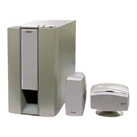
The SA-VE535H system consists of one
unit of SA-WMS535 and five units of SS-
MS535.
For the U.S. model
AUDIO POWER SPECIFICATIONS
POWER OUTPUT AND TOTAL HARMONIC DISTORTION:
with 6 ohm loads both channels driven, from 20 – 200 Hz;
rated 150 watts per channel minimum RMS power, with
no more than 0.8% total harmonic distortion from
250 milliwatts to rated output.
SS-MS535 (front, center, and rear speakers)
Speaker system
2 way, magnetically shielded
Speaker units
Woofer: 5.7 cm (2
cone type
Tweeter: 2.5 cm (1 in.),
balance dome type
Enclosure type
Bass reflex
Rated impedance
8 ohms
Power handling capacity
Maximum input power: 120 watts
Sensitivity level
85 dB (1 W, 1 m)
Frequency range
120 Hz – 50,000 Hz
Dimensions (w/h/d)
When attached speaker grille:
Approx. 98 × 168 × 137 mm
(3
× 6
× 5
7/8
5/8
When attached supplied
speaker stand:
Approx.168 × 135 × 150 mm
(6
× 5
× 6 in.)
5/8
3/8
(pointed upwards)
Approx.168 × 127 × 150 mm
(6
× 5 × 6 in.)
5/8
(pointed downwards)
Mass
When attached speaker grille:
Approx. 1.3 kg (2 lb 14 oz)
When attached supplied
speaker stand:
Approx. 1.4 kg (3 lb 2 oz)
Sony Corporation
9-873-648-02
2002D0400-1
Home Audio Company
© 2002. 04
Published by Sony Engineering Corporation
SA-WMS535
(front and rear)
SPECIFICATIONS
in.),
1/4
in.)
1/2
SA-VE535H/WMS535/
SS-MS535
SS-MS535
(center)
SA-WMS535 (subwoofer)
Speaker system
Active subwoofer,
magnetically shielded
Speaker unit
Woofer: 20 cm (8 in.),
cone type
Enclosure type
Advanced SAW type
Reproduction frequency range
26 Hz – 250 Hz
Continuous RMS power output
150 W (6 ohms 20 Hz –
20 kHz, 0.8% THD)
Inputs
LINE IN (input pin jack)
General
Power requirements
US, Canadian model:
120 V AC, 60 Hz
AEP, UK model:
220 – 230 V AC, 50/60 Hz
E model:
110 – 120 V/220 – 240 V AC,
50/60 Hz
Power consumptions
70 W
1 W (standby mode)
Dimensions (w/h/d)
Approx. 230 × 395 × 447 mm
× 15
(9
1/8
including front grille
Mass
Approx. 13.3 kg (29 lb 5.14 oz)
Supplied accessories
Foot pads (16)
Center speaker stand (1)
Screw (for the center speaker stand) (1)
Washer (for the center speaker stand) (1)
Audio connecting cord (1)
Speaker connecting cords, 10 m (32 ft 9
Speaker connecting cords, 3.5 m (11 ft 6 in.) (3)
Design and specifications are subject to change without
notice.
MICRO SATELLITE SYSTEM
SS-MS535
US Model
Canadian Model
AEP Model
UK Model
E Model
× 17
in.),
5/8
5/8
in.) (2)
3/4
1
Advertisement
Table of Contents

Related Manuals for Sony SA-VE535H


Summary of Contents for Sony SA-VE535H
- Page 1 SS-MS535 SERVICE MANUAL US Model Canadian Model Ver 1.1 2002. 04 AEP Model UK Model E Model The SA-VE535H system consists of one unit of SA-WMS535 and five units of SS- SA-WMS535 SS-MS535 SS-MS535 MS535. (front and rear) (center) SPECIFICATIONS For the U.S.
-
Page 2: Table Of Contents
LES COMPOSANTS IDENTIFIÉS PAR UNE MARQUE 0 SUR LES DIAGRAMMES SCHÉMATIQUES ET LA LISTE DES PIÈCES SONT CRITIQUES POUR LA SÉCURITÉ DE FONCTIONNEMENT. NE REMPLACER CES COMPOSANTS QUE PAR DES PIÈCES SONY DONT LES NUMÉROS SONT DONNÉS DANS CE MANUEL OU DANS LES SUPPLÉMENTS PUBLIÉS PAR SONY. -
Page 3: Diagrams
SA-VE535H/WMS535/SS-MS535 SECTION 1 DIAGRAMS 1-1. CIRCUIT BOARDS LOCATION (SA-WMS535) POWER board AUTO POWER board LED board MAIN board POWER SWITCH board CONTROL board... - Page 4 SA-VE535H/WMS535/SS-MS535 • Semiconductor Note on Schematic Diagram: Location • All capacitors are in µF unless otherwise noted. pF: µµF Ref. No. Location 50 WV or less are not indicated except for electrolytics D201 and tantalums. D202 • All resistors are in Ω and...
-
Page 5: Printed Wiring Boards (Sa-Wms535)
SA-VE535H/WMS535/SS-MS535 1-2. PRINTED WIRING BOARDS (SA-WMS535) • Refer to page 3 for Circuit Boards Location. J101 S701 LINE POWER MAIN BOARD SAVE AUTO (CHASSIS) S701 R714 R708 R707 D704 R706 Q703 C106 R705 R712 C702 D703 JW78 IC701 Q702 T501... -
Page 6: Schematic Diagram (Sa-Wms535)
SA-VE535H/WMS535/SS-MS535 1-3. SCHEMATIC DIAGRAM (SA-WMS535) R203 S201 IC202(1/2) IC203(1/2) IC201 R201 C204 IC203(2/2) C202 C203 R212 R219 R220 IC102(2/2) C201 R202 R204 R111 R205 CN101 CN201 C105 R210 R108 R206 IC202(2/2) R213 IC204(1/2) C207 IC101(2/2) C208 RV201 D201 J101 C102... -
Page 7: Exploded Views
SA-VE535H/WMS535/SS-MS535 SECTION 2 EXPLODED VIEWS NOTE: • The mechanical parts with no reference • Color Indication of Appearance Parts The components identified by mark 0 or dotted line with mark number in the exploded views are not supplied. Example : 0 are critical for safety. -
Page 8: Rear Panel Section (Sa-Wms535)
SA-VE535H/WMS535/SS-MS535 2-2. REAR PANEL SECTION (SA-WMS535) not supplied not supplied not supplied T601 F601 not supplied supplied F602 not supplied T501 not supplied F501 not supplied F502 not supplied not supplied The components identified by Les composants identifiés par une... -
Page 9: Front And Rear, Center Speaker (Ss-Ms535)
SA-VE535H/WMS535/SS-MS535 2-3. FRONT AND REAR, CENTER SPEAKER (SS-MS535) not supplied not supplied Ref. No. Part No. Description Remark Ref. No. Part No. Description Remark X-4954-607-1 FRAME (V) ASSY, GRILLE (vertical type) 4-239-555-01 TW-BASE X-4954-608-1 FRAME (H) ASSY, GRILLE (holizontal type) -
Page 10: Electrical Parts List
SA-VE535H/WMS535/SS-MS535 SECTION 3 AUTO POWER ELECTRICAL PARTS LIST CONTROL NOTE: • Due to standardization, replacements in • Items marked “*” are not stocked since The components identified by mark 0 or dotted line with mark the parts list may be different from the they are seldom required for routine service. - Page 11 SA-VE535H/WMS535/SS-MS535 CONTROL MAIN Ref. No. Part No. Description Remark Ref. No. Part No. Description Remark R206 1-249-429-11 CARBON 1/4W C310 1-117-162-11 FILM 0.01uF 100V R207 1-249-437-11 CARBON 1/4W C311 1-136-165-00 FILM 0.1uF R208 1-249-429-11 CARBON 1/4W C312 1-130-471-00 MYLAR 0.001uF...
- Page 12 SA-VE535H/WMS535/SS-MS535 MAIN Ref. No. Part No. Description Remark Ref. No. Part No. Description Remark D704 8-719-911-19 DIODE 1SS133T-72 R308 1-249-408-11 CARBON 1/4W 0 R309 1-249-408-11 CARBON 1/4W 0 R310 < IC > 1-249-408-11 CARBON 1/4W R311 1-249-429-11 CARBON 1/4W IC101...
- Page 13 SA-VE535H/WMS535/SS-MS535 MAIN POWER POWER SWITCH Ref. No. Part No. Description Remark Ref. No. Part No. Description Remark R522 1-249-425-11 CARBON 4.7K 1/4W MISCELLANEOUS R701 1-249-417-11 CARBON 1/4W *************** R702 1-247-887-00 CARBON 220K 1/4W 0 56 R703 1-249-421-11 CARBON 2.2K 1/4W...
- Page 14 SA-VE535H/WMS535/SS-MS535 REVISION HISTORY Clicking the version allows you to jump to the revised page. Also, clicking the version at the upper right on the revised page allows you to jump to the next revised page. Ver. Date Description of Revision 2002.
Need help?
Do you have a question about the SA-VE535H and is the answer not in the manual?
Questions and answers