Table of Contents
Advertisement
Advertisement
Table of Contents

Related Manuals for HemoCue Hb 201 DM


Summary of Contents for HemoCue Hb 201 DM
- Page 1 HemoCue Hb 201 DM Analyzer ® Instructions for Use...
-
Page 2: Table Of Contents
CONTENTS Introduction...................... 1 Unpacking ......................2 Functional description ..................2 1.2.1 System Components ....................2 1.2.2 Analyzer overview ....................3 General operations ..................6 Getting started – Analyzer ................6 2.1.1 Power source ......................6 2.1.2 Turning on the Analyzer ..................9 2.1.3 Power saver mode ....................10 2.1.4 Turning the Analyzer off .................. - Page 3 QC Test Procedure ..................34 Stored data ....................... 36 4.4.1 Reviewing Stored Data ..................36 4.4.2 Deleting Stored Data .................... 37 4.4.3 Review Latest Download ..................37 4.4.4 Log Input ......................... 37 Maintenance ....................38 Cleaning the Cuvette holder and the optronic unit ........ 38 Cleaning the Display ..................
-
Page 4: Introduction
Usage Disclaimer The HemoCue Hb 201 DM system has flexible settings to meet different user needs. The setting options are configured in the settings menu, requiring a pin code. The selected settings are the responsibility of the local administrator. HemoCue AB does not take responsibility for user configurations that may cause system conflicts, loss of data or prevent the end-user to perform tests. -
Page 5: Unpacking
HemoCue AB or the local distributor. HemoCue Hb 201 DM Analyzer HemoCue Hb 201 DM Analyzer Instructions for 1.2 Functional description 1.2.1 System Components FIGURE 1-2 The System consists of a specially designed Analyzer (1), the HemoCue Hb 201 DM... -
Page 6: Analyzer Overview
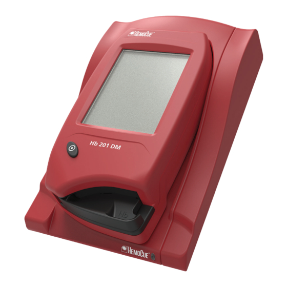
1.2.2 Analyzer overview Front panel FIGURE 1-3 The Analyzer (1) is started when the On/Off button (2) is pressed. The screen images will be visible on the Display (3). All navigation and information handling is performed by pressing the appropriate touch buttons directly on the Display (3). To perform a measurement, the Cuvette is filled with sample material and placed in the Cuvette holder (4). - Page 7 Back panel FIGURE 1-4 The following items are found on the back panel of the Analyzer. • Power inlet (1) for the Power Adapter • Power + USB signal inlet (2) for connection to the Docking Station • Built-in Barcode Scanner (3) • IR Transmitter/Receiver (4) for data transfer to/from the Docking Station The Power inlet (1) for the Power Adapter can only be used when the Analyzer is out of...
- Page 8 Placing the Analyzer in the Docking Station FIGURE 1-5 Always slide the Analyzer into and out of the Docking Station by means of the Tracks (1). Make sure the Analyzer is fully inserted. Never try to lift the Analyzer out of the Docking Station or press the Analyzer downwards into the Docking Station.
-
Page 9: General Operations
2 General operations This chapter describes the general operations necessary for Analyzer use. 2.1 Getting started – Analyzer Always follow the operating and storage conditions listed under section Technical Specifications. Allow the Analyzer to reach operating temperature before use. 2.1.1 Power source The Analyzer can be powered either by the rechargeable Battery or by a standard electrical outlet via the Power Adapter. - Page 10 Replacing the Battery FIGURE 2-2 Only the HemoCue 201 DM Battery can be used in the Analyzer. Lithium-ion battery. Never try to open the battery casing. Risk of explosion. The Battery lasts for several years. It should be replaced when it fails to retain its charge for an acceptable period.
- Page 11 Connecting the Power Adapter FIGURE 2-3 Only use the Power Adapter listed in section Technical Specifications. Other Power Adapters, although physically able to be plugged into the Analyzer, may cause serious damage or fire. a) Insert the Power Adapter’s DC plug (2) into the Power inlet (3) on the back panel of the Analyzer.
-
Page 12: Turning On The Analyzer
Turn on the Analyzer by pressing the On/ Off button (1). b) The Start Image, beginning with the HemoCue logo, will be displayed. • If the Cuvette holder is in the measuring position (see FIGURE 2-8), the following text will be displayed: Please Pull out The Cuvette Holder •... -
Page 13: Power Saver Mode
2.1.3 Power saver mode When no procedures have been performed within the time predefined in the Analyzer settings, the Analyzer will switch to power save mode. If the Analyzer is powered via the Power Adapter, the user will be logged off, the image on the display will disappear, but the power will remain on. -
Page 14: Loading The Analyzer With A Cuvette
2.1.5 Loading the Analyzer with a Cuvette The Loading position FIGURE 2-6 FIGURE 2-6 shows the Analyzer with the Cuvette holder (1) open, referred to as the Loading position. Cuvette holder Inserting a Cuvette FIGURE 2-7 Obtain a blood sample according to the procedure described in section 3 Sampling and Measuring. -
Page 15: Docking Station Led
2.2 Docking Station LED Green light FIGURE 2-9 A steady green light from the LED indicates that the Docking Station is receiving power and that the Battery is fully charged. A flashing green light from the LED indicates that the Battery in the docked Analyzer is charging. -
Page 16: How To Operate The Display
2.3 How to operate the Display 2.3.1 Display buttons FIGURE 2-11 The Buttons (1) appearing on the Display (2) activate the specific functions symbolized by the image on the button. The Buttons (1) should only be pressed using the fingertip. Do not use sharp-edged objects as these can damage the Display. - Page 17 Changing a function FIGURE 2-13 a) Keep pressing while moving the fingertip over to another button. FIGURE 2-14 b) The original button will cease to appear highlighted and the new button will appear highlighted. c) When the new Button is released, the new function will be activated.
- Page 18 Cancelling a function FIGURE 2-15 a) Keep pressing while moving the fingertip over to an area without Buttons. FIGURE 2-16 b) No Button will appear highlighted. c) When the finger is released from the Display, the first Button choice will be ignored and no action will be activated.
-
Page 19: Using The Barcode Scanner Button
2.3.2 Using the Barcode Scanner button 10-30 FIGURE 2-17 Important: Be aware of the laser radiation – 4-12 do not stare into the beam. inches To read barcodes, use the built-in Barcode Scanner in the back panel of the Analyzer. The Scanning range (3) of the Barcode Scanner, is approximately 10–30 cm (4–12 inches) from the Scanner. -
Page 20: Main Menu And Help
2.3.3 Main Menu and Help FIGURE 2-18 08/09/03 10:55 AM FIGURE 2-18 is referred to as the Main Menu. JAMES SMITH It is displayed as the Startup Image for all Tests, Setting procedures, etc. The Help button (1) may be used to display information about other buttons, procedures, etc. -
Page 21: Display Buttons And Symbols
Display buttons and symbols 2.4.1 Navigation buttons Button Designation Function Erase button Erases the last input. Previous image Returns to the previous image. button Note that inputs/changes made in the current image will not be saved. Text mode button Switches to text input mode. Numeric mode Switches to the numeric input mode. -
Page 22: Procedure Buttons
2.4.2 Procedure buttons Button Designation Function Patient test button Activates the Patient Test procedure. STAT test button Activates the STAT (Short Turn Around Time) Test procedure. QC test button Activates the QC (Quality Control) Test procedure. Stored data button Activates the Stored Data function. Settings button Activates the Settings menu. -
Page 23: Other Display Buttons
2.4.3 Other display buttons Button Designation Function Help button Displays help regarding other buttons, procedures, etc. Confirm button Saves text or numbers and/or displays the next screen image. All inputs/changes will be saved. Log Out button Logs out the operator. The Log Out button is only displayed if the Operator ID is required. - Page 24 Button Designation Function Letter buttons Allows input of a text. Example: To enter a “G” – press once To enter an “H” – press twice To enter an “I”– press three times Only capital letters will be entered. Lower-case letters can be entered into the Analyzer by means of the Barcode Scanner.
-
Page 25: Display Symbols
Button Designation Function No button The entered information will not be stored. Continue button Continues the current operation. Continue Statistics button Displays statistics on the chosen subject. 2.4.4 Display symbols Symbol Designation Function Battery Indicates the voltage status of the Battery in four levels. - Page 26 Symbol Designation Function Small hourglass When the small hourglass is displayed, the instrument is in a measuring or blanking state. When displayed in the Main Menu, only Settings and Stored Data functions are available. It is also possible to log out. Waste bin Indicates that a result has been rejected.
-
Page 27: Entering Information With Letters And Digits
2.4.5 Entering information with letters and digits 08/09/03 10:55 AM FIGURE 2-19 Inputs to the Analyzer such as Operator ID, Patient ID, etc. can be made via the display Enter or via the Barcode Scanner. Operator ID The display can be set to two different modes, text mode for entering letters (including a few special characters) and numeric mode for entering digits. - Page 28 Text mode FIGURE 2-20 Operator ID Only capital letters and a few special characters can be used in the text mode. Lower-case letters can only be entered into the Analyzer by means of the Barcode Scanner. a) In the text mode, inputs are made using the Letter buttons (1) and the Special Character button (2).
- Page 29 Numeric mode FIGURE 2-21 Operator ID a) In the numeric mode, inputs are made using the Digit buttons (1). b) The Erase button (2) erases the last input. c) If a letter or a special character is to be entered, switch to the text input mode by pressing the Text mode button (3).
-
Page 30: Sampling And Measuring
3 Sampling and Measuring This chapter describes how to obtain and measure a sample. Capillary, venous or arterial whole blood may be used. Capillary blood Be aware that peripheral circulatory failure of the patient could affect the result of a capillary sample. - Page 31 FIGURE 3-3 c) Using your thumb, lightly press the finger from the top of the knuckle towards the tip. This stimulates the blood flow towards the sampling point. FIGURE 3-4 d) Whilst lightly pressing towards the fingertip, puncture the finger using a lancet. FIGURE 3-5 e) Wipe away the first 2 or 3 drops of blood.
- Page 32 FIGURE 3-8 h) Visually inspect the Cuvette. Important: If the Cuvette is not completely filled with blood or if there are air bubbles, discard and fill a new Cuvette. Small bubbles around the filling end can be ignored. FIGURE 3-9 i) Place the filled Cuvette into the Cuvette holder.
-
Page 33: Control Material, Venous Or Arterial Blood
Control Material, Venous or Arterial Blood Always wear protective gloves. Handle blood with care, as it may be infectious. Follow local safety procedures for disposal of used Cuvettes. Appropriate anticoagulants in solid form (eg EDTA, heparin or heparin/fluoride) may be used. -
Page 34: Routine Use
4 Routine Use This chapter describes the procedure for performing Patient Tests, STAT Tests and QC Tests, as well as describing the process of reviewing stored data. Patient Test Procedure The Patient Test procedure may vary, depending on which information requirements have been activated in the Settings. - Page 35 3. Fill and insert a Cuvette as described in section 3 Sampling and Measuring. The result will be displayed when all required information has been entered and the measurement has been completed. To add comments to the result, press the Comment input button. The result will remain on the display even if the Cuvette holder is pulled out, allowing for examination of the Cuvette before comments are made.
-
Page 36: Stat Test Procedure
STAT Test Procedure The STAT Test fulfils the same function as a Patient Test but can be performed by overriding the requirement of performing any type of QC Test. When performing a STAT Test, it is optional whether or not to enter Cuvette Batch, Patient ID or Lab Number in order to make the measuring procedure quicker. -
Page 37: Qc Test Procedure
QC Test Procedure Based on the settings made for the QC Test Reminder, the QC Reminder icon will be displayed in the Main menu to warn of an impending QC lockout. If the impending QC is not performed within the pre-defined reminder time, the Analyzer will perform a lockout. - Page 38 The result will be displayed when all required information has been entered and the measurement has been completed. For a result within the Approved area (the blank area), the Qualitative Test Result will indicate “Pass”. For a result within the Warning area (the dotted area), the Qualitative Test Result will indicate “Pass, Warning”.
-
Page 39: Stored Data
Stored data 4.4.1 Reviewing Stored Data Access to the Stored Data functions is dependent on the operator’s user level and on the predefined setting of Operator ID use. Only a Supervisor can delete data, change an accepted or rejected result, or add comments. In the Main Menu, press the Stored Data button. -
Page 40: Deleting Stored Data
4.4.3 Review Latest Download When the Latest Download button is pressed in the Stored Data menu, data regarding the latest information exchange with the HemoCue 201 DM - DMS Software or an Observation Reviewer is displayed. Press the Confirm button. -
Page 41: Maintenance
5 Maintenance This chapter describes the maintenance procedure for the Analyzer. 5.1 Cleaning the Cuvette holder and the optronic unit The Cuvette holder should be cleaned after each day of use. A dirty optronic unit may cause the Analyzer to display an error code. To clean the Cuvette holder and the optronic unit, proceed as follows: a) Check that the Analyzer is turned off. - Page 42 To clean the optronic unit, push the HemoCue Cleaner into the opening of the optronic unit. h) Move the HemoCue Cleaner from the right to the left 5–10 times, and then pull it out. i) If the HemoCue Cleaner is stained, repeat with a new HemoCue Cleaner.
-
Page 43: Cleaning The Display
5.2 Cleaning the Display The display can be cleaned with alcohol, without additives. 5.3 Cleaning of the Analyzer Outer case and the Docking Station FIGURE 5-4 a) Make sure that the Analyzer is turned off. The display should be blank. b) The outer case of the Analyzer and the Docking Station may be cleaned with alcohol or a mild soap solution. -
Page 44: Calibrating The Display
5.4 Calibrating the Display If the function on the display is not responding when pressed, the display may need to be recalibrated. FIGURE 5-5 a) Make sure that the Analyzer is turned off. The display should be blank. b) To recalibrate the display, press the On/ Off button (1) for at least 10 seconds. -
Page 45: Troubleshooting
This chapter describes the Error Codes that may be displayed while using the Analyzer. If you are unable to resolve the problem by following this troubleshooting guide, please contact the local HemoCue distributor or HemoCue AB. Customers in the US should contact HemoCue America, Technical Support. There are no serviceable parts inside the Analyzer. - Page 46 Symptom Explanation Action The absorbance is too Check that the Analyzer and high. Cuvettes are used according to the Light blocking item in the Instructions for Use and relevant Cuvette holder. package insert. b) Analyzer needs service. Contact the distributor. Hardware Error Analyzer needs service.
- Page 47 Symptom Explanation Action The electronic self-test Analyzer needs service. Contact the failed. distributor. The communication self-test failed. The Analyzer may not work properly when connected to a docking station.This is stored as a failed Electronic QC Test (EQC) in the Analyzer Log book. The electronic self-test Turn off the Analyzer and clean the failed.
- Page 48 Symptom Explanation Action No characters The Analyzer is not 1a) Check that the Power Adapter is on the display receiving power. connected to the power supply. 2) If on battery power, 1b) Check that the Power Adapter is the Battery needs to securely connected to the Analyzer be recharged.
- Page 49 Disconnect and then reconnect the 2) Steady red light Power Adapter. - internal error in the 2b) Contact HemoCue AB or the Docking Station. distributor. Analyzer not No charging of the Battery. Check that the Analyzer is properly charged docked.
-
Page 50: Specifications
HemoCue Hb 201 Microcuvettes. The HemoCue Hb 201 Microcuvettes are for In Vitro Diagnostic use only. The HemoCue Hb 201 DM Analyzer is only to be used with HemoCue Hb 201 Microcuvettes. Principles of the method and procedure The Cuvette serves both as a pipette and as a measuring cuvette and is for single use only. -
Page 51: Quality Control
Quality Control The HemoCue Hb 201 DM Analyzer has an internal quality control, the self-test. Every time the Analyzer is turned on, it will automatically verify the performance of the Analyzer. This test is performed every eighth hour if the Analyzer is left turned on. The result of the self-test is stored as an EQC (Electronic Quality Control). -
Page 52: Emc And Electrical Safety
The electromagnetic environment in which the HemoCue Hb 201 DM system will be operated should be evaluated prior to operation of the device. Do not use the HemoCue Hb 201 DM system in close proximity to sources of strong electromagnetic radiation (e.g. -
Page 53: Materials Required But Not Provided
7.10 Materials required but not provided • HemoCue Hb 201 Microcuvettes • Lancet* • Pipette or other transfer device** • Lint-free wipe • Hydrophobic surface ** * For capillary samples ** For venous/arterial samples 7.11 Spare parts • Power Adapter •... -
Page 54: Symbols Used
7.13 Symbols used Consult instructions for Caution CE mark Biological risk In Vitro diagnostic medical Temperature limitation device Manufacturer Humidity limitation Alternating current Catalogue number Serial number Ethernet DC inlet Lithium-ion Battery. Only valid within the Danger of explosion. European Community. Replace the battery with Indicates separate the same type... -
Page 55: References
7.14 References Dacie and Lewis, Practical Haematology, Ninth Edition, 2001 HemoCue Hb 201 Microcuvettes Package Insert Makarem, A. In clinical Chemistry: Principles and Techniques, 2nd ed., Henry, R.J., Cannon, D.C., and Winkelman, J.W., Harper and Row, Hagerstown, M.D., 1974, pp. 1125–1147 Reference and Selected Procedures for the Quantitative Determination of Hemoglobin in Blood;... -
Page 56: Technical Specifications
FW7556M/06: 6 V /2500 mA FW8001/06: 5.9 V /3000 mA Battery HemoCue Li-ion rechargeable power battery 201 DM 3.6V 2.6Ah Battery capacity ≥ 120 tests/100 hours using the Barcode Scanner and a power save setting of 5 minutes Battery charging time 75% of its capacity <...
Need help?
Do you have a question about the Hb 201 DM and is the answer not in the manual?
Questions and answers