
Related Manuals for Siemens GMSG-GCB


Summary of Contents for Siemens GMSG-GCB
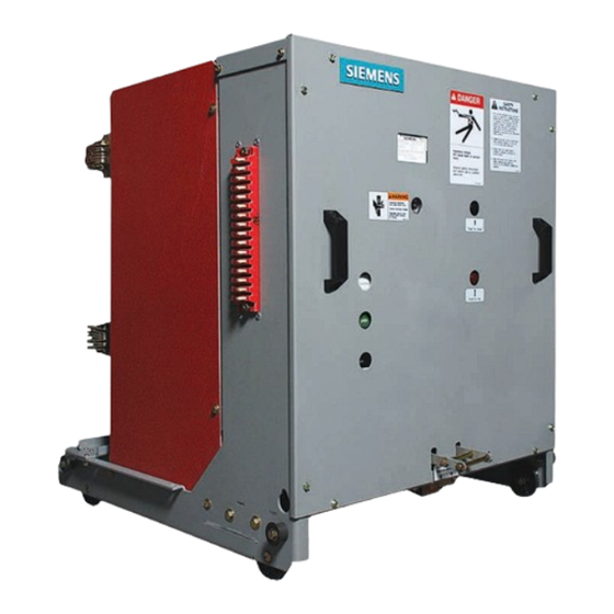
- Page 1 Instruction manual Types GMSG and GMSG-GCB 5 kV to 15 kV vacuum circuit breakers Installation operation maintenance E50001-F710-A231-V3-4A00 www.usa.siemens.com/mvswitchgear...
- Page 2 Siemens reserves the right to make changes 50 volts or more, and shall, at a minimum, be in the specifications shown herein or to make...
-
Page 3: Table Of Contents
The sales contract contains the entire obligation of Siemens Industry, Inc. The warranty contained in the contract between the parties is the sole warranty of Siemens Industry, Inc. Any statements contained herein do not create new warranties or modify the... -
Page 4: Introduction
Follow all safety instructions contained herein. Important Signal words The types GMSG and GMSG-GCB vacuum The signal words "danger," "warning" and circuit breakers are designed to meet all "caution" used in this instruction manual applicable ANSI, NEMA and IEEE standards. - Page 5 Check For medium-voltage customer service issues, to be certain that the indicator flags read contact Siemens at +1 (800) 347-6659 or +1 OPEN and DISCHARGED. (919) 365-2200 outside the U.S. 3. Always let an interlock device or safety mechanism perform its function without forcing or defeating the device.
-
Page 6: Receiving, Handling And Storage
Important: The manner in which visible the receiving, handling and storage shipping damage is identified by consignee instructions for a type GMSG or GMSG-GCB prior to signing the delivery receipt can vacuum circuit breaker shipped separately determine the outcome of any damage claim from the switchgear. - Page 7 Siemens cannot be held liable for repairs. Equipment must be inspected by carrier prior Siemens will not be held liable for repairs in to handling after receipt. This eliminates loss any case where repair work was performed due to claims by carrier that the equipment prior to authorization from Siemens.
- Page 8 Storage procedure 1. Whenever possible, install the circuit breaker in its assigned switchgear enclosure for storage. Follow instructions contained in the switchgear instruction manual, E50001-F710-A230-X-XXXX for type GM-SG non-arc-resistant or E50001- F710-A254-X-XXXX for type GM-SG-AR arc-resistant switchgear. 2. When the circuit breaker needs to be placed on its pallet for storage, be sure the unit is securely bolted to the pallet and covered with polyethylene film at...
-
Page 9: Installation Checks And Functional Tests
Installation checks and functional tests Hazardous voltage and high-speed moving parts. Will cause death, serious injury and property damage. Read instruction manuals, observe safety instructions and use qualified personnel. Opening this circuit breaker or switch Introduction This section provides a description of the accomplishes the same result: control power is disconnected. - Page 10 Heavy weight. Can result in death, serious injury or property damage. Observe all handling instructions in this instruction manual to prevent tipping or dropping of equipment. Removal from cell in indoor switchgear (if Removal from cell in outdoor non-walk-in not on raised pad) and Shelter-Clad enclosures or for indoor switchgear installed on a raised pad outdoor switchgear...
- Page 11 Siemens circuit breaker lifting device or visible is cylindrical, and the shoulder of the Siemens lifting sling and a suitable crane. racking-mechanism shaft is hidden by a shroud until the engagement procedure 7. Lift the two extension rails and withdraw starts.
- Page 12 Note: For arc-resistant type GM-SG-AR Physical inspections switchgear, if control power is not available 1. Verify the rating of the circuit breaker is and the circuit breaker compartment door is compatible with both the system and the closed, the circuit breaker can be opened switchgear.
- Page 13 (if furnished) to the circuit breaker on page 28) with a light film of breaker as shown in Figure 5: Split-plug Siemens contact lubricant number jumper connected to circuit breaker. The 15-172-791-233. split-plug jumper is secured over the...
-
Page 14: Vacuum Interrupter/Operator
Spring-charging motor Secondary disconnect Introduction A type GMSG vacuum circuit breaker consists The type GMSG and type GMSG-GCB vacuum of three vacuum interrupters, a stored-energy circuit breakers are of drawout construction operating mechanism, necessary electrical designed for use in medium-voltage, metal- controls and interlock devices, disconnect clad switchgear. - Page 15 Ceramic insulator type GMSG vacuum circuit breaker. Arc shield Type GMSG-GCB generator circuit breakers Fixed contact The type GMSG-GCB generator circuit breaker Moving contact is a special variant of the type GMSG circuit Ceramic insulator breaker family. The circuit breaker design,...
- Page 16 ANSI/IEEE C37.04-1999, clause 6.9 (for type GMSG) or ANSI/IEEE C37.013, clause 6.3.8 (for type GMSG-GCB). The operation of the stored- energy mechanism will be discussed later in this section. The vacuum circuit breaker consists of two sub-assemblies.
- Page 17 Construction Refer to Figure 12: Interrupting/operating Shown with outer-phase barriers installed mechanism module on page 17, Figure 13: Operating mechanism controls and indicators on page 18, Figure 14: Type GMSG vacuum circuit breaker pole section on page 19 and Figure 15: Stored-energy operating mechanism on page 20.
- Page 18 Vacuum interrupter Refer to Figure 9: Vacuum interrupter cutaway view on page 15. The moving-contact (36.0) motion is aligned and stabilized by guide bushing (35.0). The 53.0 metal bellows (34.0) follows the travel of contact (36.0) and seals the vacuum 54.0 55.0 interrupter against the surrounding...
- Page 19 Figure 14: Type GMSG vacuum circuit breaker pole section 16.0 Insulator 20.0 20.0 Upper pole support (pole head) 27.0 27.0 Upper-connection terminal 31.2 28.0 Strut 16.0 28.1 Centering ring 29.0 Lower-connection terminal 29.1 Flexible connector 29.2 Terminal clamp 30.0 Vacuum interrupter 31.0 Stationary contact 28.0...
- Page 20 Figure 15: Stored-energy operating mechanism 50.3.1 62.3 62.5 55.2 50.3 50.2 62.2 62.5.2 68.0 50.1 53.0 55.1 62.6 53.1 50.4.1 62.0 54.1 55.0 54.0 50.4 62.8 54.2 64.0 64.2 68.1 58.0 63.7 63.0 63.1 59.0 64.3.1 61.8 64.3 63.5 60.0 50.1 Manual-spring charging port 55.0...
- Page 21 ANSI/IEEE C37.04-1999, actions. clause 6.9 (for type GMSG) or ANSI/IEEE 3. Means of transmitting force and motion C37.013, clause 6.3.8 (for type GMSG-GCB). to each of three poles. When the stored-energy mechanism has been 4. Operate all of these functions...
- Page 22 Closing Refer to Figure 15: Stored-energy operating mechanism on page 20 and Figure 16: Use of manual-spring operating crank on page 22. If the circuit breaker is to be closed locally, the 50.0 closing spring is released by pressing the 50.1 53.0 close button (53.0).
- Page 23 0.3 seconds, per ANSI/IEEE C37.06- undervoltage) (optional) 2009. The indirect release provides for the While the type GMSG-GCB generator circuit conversion of modest-control signals into breaker is capable of rapid reclosing duty, fast powerful mechanical-energy impulses. It is...
- Page 24 Figure 17: Operator sequence operation diagram Closing Closed voltage applied. Anti-pumping feature (52Y) assures a continuously applied closing command does not cause the circuit breaker to reclose automatically after it has tripped out on a fault. Undervoltage device Spring-charge motor Continuous 27 picks up.
- Page 25 Figure 18: Typical elementary diagram 88 (M1) - Spring-charging motor 52a (S1) - Auxiliary switch is open when circuit breaker is open 52b (S1) - Auxiliary switch is closed when circuit breaker is open LS3 (S3) - Anti-pump circuit is open when closing (SD) (SD) (SD)
- Page 26 These releases are mechanical-energy storage Shown charged devices. Their internal springs are charged as a consequence of the circuit breaker 23.0 33.0 31.0 mechanism operation. This energy is released 27.0 upon application or removal (as appropriate) 25.0 21.0 of applicable control voltages (refer to Figure 19: Construction of secondary shunt release 13.0 and Figure 20: Latch details on page 26 and...
- Page 27 Construction and mode of operation of Position A: locked secondary release and undervoltage release Refer to Figure 19: Construction of secondary shunt release and Figure 20: Latch details on 29.0 page 26 and Figure 21: Undervoltage lock/ operate selection. 23.0 The release consists of a spring power-storing mechanism, a latching device and an electromagnet.
- Page 28 Following every tripping operation, the striker Shock absorber pin (23.0) must be reset to its normal position A type GMSG vacuum circuit breaker is by loading the spring (31). This takes place equipped with a sealed, oil-filled, viscous automatically via the operating mechanism of damper or shock absorber (61.8) (referto the circuit breaker.
- Page 29 Closed circuit breaker racking interlock Ground disconnect Circuit breaker frame Racking mechanism release handle Rating interlock Trip-free interlock Figure 28: Circuit breaker interlocks and ground disconnect Figure 26: MOC switch operating arm on a circuit breaker Mechanism-operated cell (MOC) switch (optional) Figure 26: MOC switch operating arm on a circuit breaker and Figure 27: MOC (bottom)
- Page 30 Figure 29: Circuit breaker compartment (up to 50 kA shown) 11.0 10.0 12.0 Interface blocking plate (rating interlock) MOC switch terminals Racking mechanism TOC switch terminals Ground bar Shutter-operating linkage 10.0 Guide rails Shutter (behind barrier) Trip-free and racking interlock padlock provisions 11.0 CT barrier MOC switch operator...
- Page 31 Trip-free interlock Type GMSG (not type GMSG-GCB) circuit Figure 28: Circuit breaker interlocks and breaker rating interlocks ground disconnect on page 29 shows the Type GMSG (not type GMSG-GCB) vacuum devices providing the trip-free interlock circuit breakers rated up to 50 kA are function.
- Page 32 The type GMSG vacuum circuit breaker is "Rating interlock". designed for easy movement into and out of the metal-clad switchgear assembly. Siemens integrated electric-racking system (SIERS) (optional) A section of indoor or Shelter-Clad switchgear An electrical racking system integrated into...
- Page 33 The vehicle supports the vaccum interrupter/operator module, providing mobility and fully coordinated application in Siemens type GM-SG or type GM-SG-AR switchgear. Successful coordinated application of the fully assembled type GMSG vacuum circuit breaker...
- Page 34 This shroud must be moved rearward to insert the racking- B. Type GMSG-GCB (not type GMSG) crank socket in order to engage the generator circuit breaker rating racking shaft. With the plunger down...
- Page 35 The spring dump cam profile on the C. Trip-free interlock position - racking mechanism raises the spring mechanical interlock dump/trip-free interlock upon insertion In order to prevent the motor- charging of the circuit breaker into the circuit from "making and breaking" as compartment, or upon withdrawal the circuit breaker and cubicle from the compartment.
-
Page 36: Maintenance
C37.04, section 4 together with C37.010, requirements that pertain to their respective section 4 for type GMSG non-generator circuit job assignments. breakers. For type GMSG-GCB generator This instruction manual should be reviewed circuit breakers, these service conditions are and retained in a location readily accessible defined in ANSI/IEEE C37.20.2, section 8.1... - Page 37 Deep sockets: 19 mm not covered sufficiently for the Purchaser's Torque wrench: 0 - 150 Nm purposes, the matter should be referred to Siemens at +1 (800) 347-6659 or +1 (919) (0 - 100 ft-lbs). 365-2200 outside the U.S. SAE (U.S. customary):...
- Page 38 Failure to maintain the equipment can result in death, serious injury, property damage or product failure, and can prevent successful functioning of connected apparatus. The instructions contained herein should be carefully reviewed, understood and followed. The maintenance tasks in Table 1 must be performed regularly. Inspection items and tests Primary-power path checks Cleanliness check...
- Page 39 Removal from switchgear Checks of the primary power path Prior to performing any inspection or The primary power path consists of three maintenance checks or tests, the circuit vacuum interrupters and three upper-primary breaker must be removed from the and three lower-primary disconnects. These switchgear.
- Page 40 (strips and fingers) are to be wiped clean, and These intervals assume the circuit breaker is a film of Siemens contact lubricant (15-172- Table 2: Maintenance and operated under “usual service conditions” as 791-233) applied. Avoid getting contact lubrication schedule discussed in ANSI/IEEE C37.20.2, section 8.1,...
- Page 41 Figure 35: Operator mechanism lubrication Klüber L32 or Klüber L32N Typical for all three phases...
- Page 42 Fastener check The white-erosion mark is located in the Inspect all fasteners for tightness. Both keyway (or slot) on the movable stem of locknuts and retaining rings are used. Replace the vacuum interrupter, near the plastic- any fasteners that appear to have been guide bushing.
- Page 43 Hazardous voltage and high-speed moving parts. Will cause death, serious injury and property damage. Read instruction manuals, observe safety instructions and use qualified personnel. Wiring and terminals check Automatic spring-charging check (control 1. Physically check all of the circuit breaker power required) wiring for evidence of abrasion, cuts, Repeat the automatic spring-charging check...
- Page 44 The vacuum interrupter type designation is labeled on the vacuum interrupter. If the vacuum interrupter installed does not match that indicated in this table, contact the nearest Siemens representative. If you need assistance achieving the indicated stroke setting, contact the nearest Siemens representative.
- Page 45 Figure 37: Typical vacuum interrupter contact life curves Load graph "A" vacuum interrupter type VS-17006 Note: Right-hand vertical segment of curve is located at the maximum symmetrical interrupting current rating of the circuit breaker, as indicated in Table 3: Typical vacuum interrupter contact life and stroke on page 44. Permissible operating cycles 100,000 50,000...
- Page 46 Figure 37: Typical vacuum interrupter contact life curves (continued) Load graph "B" vacuum interrupter type VS-17040 Note: Right-hand vertical segment of curve is located at the maximum symmetrical interrupting current rating of the circuit breaker, as indicated in Table 3: Typical vacuum interrupter contact life and stroke on page 44. Permissible operating cycles 100,000 50,000...
- Page 47 Figure 37: Typical vacuum interrupter contact life curves (continued) Load graph "C" vacuum interrupter type VS-15052 Note: Right-hand vertical segment of curve is located at the maximum symmetrical interrupting current rating of the circuit breaker, as indicated in Table 3: Typical vacuum interrupter contact life and stroke on page 44. Permissible operating cycles 100,000 50,000...
- Page 48 Figure 37: Typical vacuum interrupter contact life curves (continued) Load graph "D" vacuum interrupter type VS-17085 Note: Right-hand vertical segment of curve is located at the maximum symmetrical interrupting current rating of the circuit breaker, as indicated in Table 3: Typical vacuum interrupter contact life and stroke on page 44. Permissible operating cycles 100,000 50,000...
- Page 49 Electrical close and trip check Vacuum-interrupter mechanical check (control power required) Refer to Figure 38: Lower pole support with A check of the circuit breaker control circuits insulated coupler, Figure 39: Primary contact is performed while the unit is still connected closed and insulated coupler disconnected to the switchgear by the split- plug jumper.
- Page 50 High-potential tests employ hazardous voltages. Will cause death and serious injury. Follow safe procedures, exclude unnecessary personnel and use safety barriers. Keep away from the circuit breaker during application of test voltages. Disconnect the split plug jumper from between the circuit breaker and switchgear before conducting high-potential tests.
- Page 51 Table 4: High-potential test voltages *Megger is a registered trademark of Megger Group, Rated maximum voltage Rated power-frequency withstand Field-test voltage Ltd. kV (rms) kV (rms) kV (rms) kV dc 4.76 14.25 20.2 8.25 38.2 15.0 38.2 15.0 generator 28.5 40.3 circuit breaker Vacuum-integrity test procedure...
- Page 52 2. Remove phase barriers as shown in Figure 7: Circuit breaker primary disconnects on page 13. Table 5: Maximum contact Contact resistance (micro-ohms) Continuous resistance Type GMSG Type GMSG-GCB current rating non-generator circuit breaker generator circuit breaker 25 kA All others 63 kA 40 kA...
-
Page 53: Overhaul
GMSG 10,000 section, provide maintenance personnel with when required: GMSG-GCB 10,000 a guide to identifying and correcting possible Vacuum interrupters as determined by malfunctions of the type GMSG vacuum vacuum-integrity test, contact erosion or circuit breaker. - Page 54 1.0 Removing the vacuum interrupter It is recommended that vacuum interrupters 1.1 Before starting work, the circuit breaker be replaced only by a qualified Siemens field should be isolated from all primary- and service representative. The information in the control-power sources and all stored...
- Page 55 1.7 Remove bolt (31.2), lock washer and 2.6 Couple levers (48.6) and drive link (48.9) large washer at stationary contact of the to the eye bolt (36.3), using the pin vacuum interrupter (24 mm socket with supplied. Apply retention clips. extension).
- Page 56 Figure 42: Vacuum interrupter replacement illustration 20.0 31.2 28.0 30.0 28.1 29.3 29.1 29.2 36.1 36.3 48.9 48.6 48.0 40.0 48.5 20.0 Upper pole-support (pole-head) 36.1 Moving terminal 28.0 Strut 36.3 Eye bolt (or adapter) 28.1 Centering ring 40.0 Lower pole-support (pole-bottom) 29.1 Flexible connector 48.0...
- Page 57 Figure 43: Illustration showing required technique for fastening terminal-clamp hardware 30.0 Position of torque wrench to avoid undue stressing of moving contact (36.1) Holding wrench Direction of force (P) Torque wrench 29.2 Terminal clamp 36.1 29.3 29.3 Spacer (or shoulder) 30.0 Vacuum interrupter 36.1...
- Page 58 2.10 The centering ring (28.1) has been loose 3.8 Loosen locking nut on eye bolt on and floating during installation of the insulated coupler (48.0), and retain vacuum interrupter. Check that the position of the eye. Make adjustments in movable contact is free to move one-half turn increments.
-
Page 59: Maintenance And Troubleshooting
Maintenance and troubleshooting Table 7: Periodic maintenance and lubrication tasks Sub-assembly Item Inspect for 1. Cleanliness. 2. Contact erosion. Vacuum interrupter Note: Perform with manual-spring checks. 3. Vacuum integrity. Note: Perform with high-potential tests. Primary power path 1. Burnt or damaged fingers. Primary disconnects 2. - Page 60 1. Mechanical failure of operating mechanism. Check Sound of circuit breaker and contact regional service centers, the factory or closing is heard but telephone Siemens field service at +1 (800) 347- circuit breaker contacts 6659 or +1 (919) 365-2200 outside the U.S. do not close.
- Page 61 1. Mechanical failure of operating mechanism. Check and contact regional service centers, the factory or Mechanical problem telephone Siemens field service at +1 (800) 347-6659 or +1 (919) 365-2200 outside the U.S. 1. Secondary control power is de-energized or control power fuses are blown.
-
Page 62: Appendix
Appendix Table 9: Circuit breaker control data Footnotes: Control voltages, Spring charging motor Current at nominal voltage ANSI/IEEE C37.06 Close Capacitor trip Trip coil coil Inrush Value preceding slash (/) is the current Range Charging (Average) (Peak) for the standard trip coil with standard Nominal rating interrupting time. - Page 63 (195) (290) 15-GMSG-40 15-GMSG-750 (202) (304) (306) 15-GMSG-50 15-GMSG-1000 (209) (306) (308) 15-GMSG-63 (372) (377) (379) 5-GMSG-GCB-40 15-GMSG-GCB-40 (215) (311) (324) 5-GMSG-GCB-50 15-GMSG-GCB-50 (374) (379) (392) 5-GMSG-GCB-63 15-GMSG-GCB-63 (397) (408) (427) Table 12: Circuit breaker operating times (type 3AH3 operator) Spring charging time ≤...
- Page 64 Maximum Short-circuit Interrupting design voltage Withstand voltage levels Continuous current time 5, 6 Voltage range Circuit breaker type factor (k) Power Lightning kV rms frequency impulse (BIL) A rms kA rms sym ms/cycles kV rms kV peak 5-GMSG-40-xxxx-104 4.76 1,200, 2,000, 3,000, 4,000FC 83/5 5-GMSG-50-xxxx-130 4.76...
- Page 65 10,000 10,000 10,000 Table 14: Type GMSG-GCB generator circuit breaker rated values and related capabilities Footnotes: Interrupting time is based on the first current zero occurring not later than 66 ms after fault initiation, for example, %dc component <100.
- Page 66 Short-circuit (at rated Nominal Nominal Maximum Voltage Continuous maximum voltage three-phase design range Withstand voltage levels current design class MVA class voltage (V) factor (K) voltage) (I) Circuit breaker type 6, 10 Power Lightning kV rms A rms ---- frequency impulse (BIL) kA rms sym kV rms...
- Page 67 These ratings are in accordance with: Footnotes: “xxxx” in type designation refers to the continuous current rating 1,200 A, 2,000 A or 3,000 A, ANSI/IEEE C37.04-1979 Standard Rating as appropriate. The 4,000 A fan-cooled rating Structure for AC High-Voltage Circuit is achieved using a 3,000 A circuit breaker, in Breakers Rated on a Symmetrical combination with fan cooling as indicated in...
- Page 68 All product designations may be trademarks or product names of Siemens AG or supplier companies whose use by third parties for their own purposes could violate the rights of the owners.
Need help?
Do you have a question about the GMSG-GCB and is the answer not in the manual?
Questions and answers