Table of Contents
Advertisement
OWNER'S
MANUAL
MODEL NO.
944.604881
Important:
Read and fol low
all Safety Rules
and In struc tions
Be fore Op er at ing
This Equip ment
Sears Canada, Inc., Toronto, Ontario M5B 2B8
00011
18.0 HP
ELECTRIC START
42" MOWER
AUTOMATIC
LAWN TRACTOR
• Assembly
• Operation
• Maintenance
• Service and Adjustments
• Repair Parts
02494
Advertisement
Table of Contents

Related Manuals for Sears Craftsman 944.604881


Summary of Contents for Sears Craftsman 944.604881
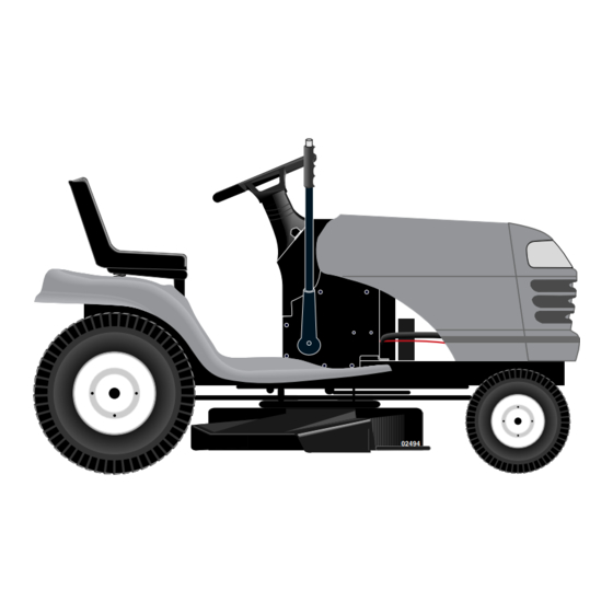
- Page 1 ELECTRIC START and In struc tions Be fore Op er at ing 42" MOWER This Equip ment AUTOMATIC LAWN TRACTOR • Assembly • Operation • Maintenance • Service and Adjustments • Repair Parts Sears Canada, Inc., Toronto, Ontario M5B 2B8...
-
Page 2: Safety Rules
SAFETY RULES SAFE OPERATION PRACTICES FOR RIDE-ON MOWERS IMPORTANT: THIS CUTTING MACHINE IS CAPABLE OF AMPUTATING HANDS AND FEET AND THROW ING OBJECTS. FAILURE TO OBSERVE THE FOLLOWING SAFETY INSTRUCTIONS COULD RESULT IN SERIOUS INJURY OR DEATH. I. GENERAL OPERATION DO NOT: Do not turn on slopes unless necessary, and then, •... -
Page 3: Table Of Contents
SAFETY RULES SAFE OPERATION PRACTICES FOR RIDE-ON MOWERS • Be sure the area is clear of other people before mowing. Stop machine if anyone enters the area. WARNING: Do not coast down a hill in neu- • Never carry passengers or children even with the blades tral, you may lose control of the trac tor. -
Page 4: Product Specifications
LIMITED TWO (2) YEAR WARRANTY ON CRAFTSMAN TRACTOR (RIDING EQUIPMENT) For two (2) years from date of purchase Sears Canada, Inc. will repair or replace at Sears option free of charge parts which are defective as a result of material or workmanship. - Page 5 UNASSEMBLED PARTS Steering Wheel Seat Steering (1) Washer Boot 17/32 x 1-3/16 x 12 Gauge Steering (1) Knob Extension Shaft Battery Steering Wheel Insert (2) Hex Bolts 1/4-20 x 3/4 (2) Keps Nuts 1/4-20 (1) Large Flat Washer Steering Wheel Adapter (1) Oil Drain Tube Keys...
-
Page 6: Assembly
ASSEMBLY Your new tractor has been assembled at the factory with exception of those parts left unassembled for shipping purposes. To ensure safe and proper operation of your tractor all parts and hardware you assemble must be tightened securely. Use the correct tools as necessary to insure proper tightness. - Page 7 ASSEMBLY • Get off seat without moving its ad just ed position. • Raise seat and tighten adjustment knob securely. DISCARD TER MI NAL PROTECTIVE CAPS TERMINAL SEAT KEPS COVER HEX BOLT SEAT PAN POSITIVE (RED) CABLE NEGATIVE (BLACK) CABLE SHOULDER BOLT 02466...
- Page 8 ASSEMBLY • Sit on seat in operating position, depress clutch/brake CHECK DECK LEVELNESS pedal and set the parking brake. For best cutting results, mower housing should be properly • Place motion control lever in neutral (N) position. leveled. See “TO LEVEL MOWER HOUSING” in the Service •...
-
Page 9: Operation
OPERATION These symbols may appear on your tractor or in literature supplied with the product. Learn and understand their mean- ing. FAST IGNITION HIGH SLOW REVERSE NEUTRAL CHOKE ENGINE START LIGHTS ON ENGINE ON PARKING BRAKE ENGINE OFF PARKING BRAKE PARKING BRAKE LOCKED UNLOCKED... - Page 10 OPERATION KNOW YOUR TRACTOR READ THIS OWNER'S MANUAL AND SAFETY RULES BEFORE OPERATING YOUR TRACTOR Compare the illustrations with your tractor to familiarize yourself with the locations of various controls and ad just ments. Save this manual for future reference. AT TACH MENT LIGHT IGNITION...
- Page 11 OPERATION The operation of any tractor can result in foreign objects thrown into the eyes, which can result in severe eye dam age. Always wear safety glass es or eye shields while op- erating your tractor or per form ing any adjustments or repairs. We rec om mend a wide vision safety mask over spectacles or stan dard safety glasses.
- Page 12 OPERATION TO ADJUST GAUGE WHEELS (See Fig. 8) TO OPERATE ON HILLS Gauge wheels are properly adjusted when they are slightly off the ground when mower is at the desired cutting height WARNING: Do not drive up or down hills with slopes greater than 15° and in operating position.
- Page 13 OPERATION BEFORE STARTING THE ENGINE NOTE: Before starting, read the warm and cold starting procedures below. • Insert key into ignition and turn key clockwise to CHECK ENGINE OIL LEVEL “START” position and release key as soon as engine • The engine in your tractor has been shipped, from the starts.
- Page 14 OPERATION • Place tractor safely on level surface with engine off and • If grass is extremely tall, it should be mowed twice to parking brake set. reduce load and possible fi re hazard from dried clip- pings. Make fi rst cut relatively high; the second to the •...
-
Page 15: Maintenance Schedule
MAINTENANCE MAINTENANCE SCHEDULE FILL IN DATES AS YOU COMPLETE REGULAR SERVICE SERVICE DATES Check Brake Operation Check Tire Pressure Check Operator Presence and Interlock Systems Check for Loose Fasteners Sharpen/Replace Mower Blades Lubrication Chart Check Battery Level Clean Battery and Terminals Check Transaxle Cooling Check V-Belts Check Engine Oil Level... -
Page 16: Maintenance
MAINTENANCE TRACTOR TRAILING EDGE UP Always observe safety rules when performing any main- BLADE te nance. CEN TER HOLE BRAKE OPERATION If tractor requires more than six (6) feet stopping distance FLAT WASHER at high speed in highest gear, then brake must be adjusted. MANDREL LOCK (See “TO ADJUST BRAKE”... - Page 17 MAINTENANCE NOTE: The original equipment battery on your tractor is SAE VISCOSITY GRADES maintenance free. Do not attempt to open or remove caps or covers. Adding or checking level of electrolyte is not nec es sary. TO CLEAN BATTERY AND TERMINALS 5W-30, 10W-30 Corrosion and dirt on the battery and terminals can cause the battery to “leak”...
- Page 18 MAINTENANCE • Unlock drain valve by pushing inward and turning coun ter clock wise. HAN DLE • To open, pull out on the drain valve. • After oil has drained completely, close and lock the drain valve by pushing inward and turning clockwise until the pin is in the locked position as shown.
- Page 19 MAINTENANCE IN-LINE FUEL FILTER (See Fig. 18) CLEANING • Clean engine, battery, seat, fi nish, etc. of all foreign The fuel fi lter should be replaced once each season. If fuel matter. fi lter becomes clogged, ob struct ing fuel fl ow to car bu re tor, re place ment is re quired.
-
Page 20: Service And Adjustments
SERVICE AND ADJUSTMENTS WARNING: TO AVOID SERIOUS INJURY, BEFORE PERFORMING ANY SER VICE OR AD JUST - MENTS: • Depress clutch/brake pedal fully and set parking brake. • Place motion control lever in neutral (N) position. • Place attachment clutch in “DISENGAGED” position. •... - Page 21 SERVICE AND ADJUSTMENTS Check adjustment on right side of tractor. Measure dis tance • Place fl at washer and clutch spring on idler pulley bolt “D” directly in front and behind the mandrel at bottom edge and secure with small retainer spring. of mower housing as shown.
- Page 22 SERVICE AND ADJUSTMENTS TO REPLACE MOWER BLADE DRIVE BELT • Engage transmission by placing freewheel control in “trans mis sion engaged” position. (See Fig. 24) • Road test tractor for proper stopping distance as stated The mower blade drive belt may be replaced without tools. above.
- Page 23 SERVICE AND ADJUSTMENTS TRANSMISSION REMOVAL/REPLACEMENT ENGINE PULLEY Should your transmission require removal for service or replacement, it should be purged after reinstallation and CLUTCHING before operating the tractor. See “PURGE TRANS MIS SION” IDLER in the Operation section of this manual. TO ADJUST STEERING WHEEL ALIGN- STA TION ARY IDLER...
- Page 24 SERVICE AND ADJUSTMENTS TO REPLACE HEADLIGHT BULB TO START ENGINE WITH A WEAK BAT TERY (See Fig. 29) • Raise hood. • Pull bulb holder out of the hole in the backside of the grill. WARNING: Lead-acid batteries gen- er ate ex plo sive gases. Keep sparks, •...
- Page 25 SERVICE AND ADJUSTMENTS ENGINE IMPORTANT: DAMAGE TO THE NEEDLE VALVE AND THE SEAT IN CARBURETOR MAY RE SULT IF SCREW IS TURNED Maintenance, repair, or replacement of the emission con- IN TOO TIGHT. trol devices and systems, which are being done at the PRELIMINARY SETTING - cus tom ers expense, may be performed by any non-road •...
-
Page 26: Storage
STORAGE Immediately prepare your tractor for storage at the end ENGINE of the season or if the tractor will not be used for 30 days or more. FUEL SYSTEM IMPORTANT: IT IS IMPORTANT TO PREVENT GUM DEPOSITS WARNING: Never store the trac tor with FROM FORMING IN ES SEN TIAL FUEL SYSTEM PARTS SUCH gas o line in the tank inside a building AS CARBURETOR, FUEL FIL TER, FUEL HOSE, OR TANK... -
Page 27: Trou Ble Shoot Ing
TROUBLESHOOTING POINTS PROBLEM CAUSE CORRECTION Will not start Out of fuel. Fill fuel tank. Engine not “CHOKED” properly. See “TO START ENGINE” in Operation section. Engine fl ooded. 3. Wait several minutes before attempting to start. Bad spark plug. Replace spark plug. Dirty air fi... - Page 28 TROUBLESHOOTING POINTS PROBLEM CAUSE CORRECTION Engine continues to run Faulty operator-safety presence control system. Check wiring, switches and connections. If not when operator leaves corrected, contact an authorized service center/ seat with attachment department. clutch engaged Poor cut - uneven 1.
- Page 29 TRACTOR - - MODEL NUMBER 944.604881 SCHEMATIC BLACK BATTERY FUSE STARTER AMMETER (OPTIONAL) BLACK WHITE SOLENOID CLUTCH / BRAKE (PEDAL UP) WHITE SEAT SWITCH IGNITION (NOT OCCUPIED) SWITCH WHITE BLACK BLACK BLACK BLACK ATT'MENT CLUTCH GROUNDING (CLUTCH OFF) BLACK CONNECTOR HOUR METER (OPTIONAL)
-
Page 30: Repair Parts - Tractor
REPAIR PARTS TRACTOR - - MODEL NUMBER 944.604881 ELECTRICAL D .C... - Page 31 REPAIR PARTS TRACTOR - - MODEL NUMBER 944.604881 ELECTRICAL PART DESCRIPTION 163495 Battery 74760412 Bolt Hex Hd 1/4-20 Unc x 3/4 176689 Box Battery 176138 Switch Interlock Push-In 175688 Harness Asm Light W/4152J 4152J Bulb Light #1156 4799J Cable Battery 6 Ga 11"red 146147 Cable Battery 175158...
- Page 32 REPAIR PARTS TRACTOR - - MODEL NUMBER 944.604881 CHASSIS AND ENCLOSURES chassis-Laser -lt.stlt_30...
- Page 33 REPAIR PARTS TRACTOR - - MODEL NUMBER 944.604881 CHASSIS AND ENCLOSURES PART DESCRIPTION 174619 Chassis Stl Stamping 176554 Drawbar, Stretch 155272 Bumper Hood/Dash 168337X011 Dash P/L STD533710 Bolt Carriage 3/8-16 x 1 174996 Panel Dash Lh 172105X010 Panel Dash Rh 17490608 Screw Thdrol 3/8-16 x 1/2 185682X558 Hood...
- Page 34 REPAIR PARTS TRACTOR - - MODEL NUMBER 944.604881 DRIVE drive-hydro.stlt_52...
- Page 35 REPAIR PARTS TRACTOR - - MODEL NUMBER 944.604881 DRIVE KEY PART KEY PART NO. NO. DESCRIPTION NO. NO. DESCRIPTION - - - - - - - - - Transaxle (See Breakdown) Peer- 137057 Spacer Axle less LTH2000 121749X Washer 25/32 x 1 1/4 x 16 Ga 165866 Rod Shift Fender Adjust LT STD581075 E-ring #5133-75...
- Page 36 REPAIR PARTS TRACTOR - - MODEL NUMBER 944.604881 STEERING ASSEMBLY steering_pl.lt_46...
- Page 37 REPAIR PARTS TRACTOR - - MODEL NUMBER 944.604881 STEERING ASSEMBLY KEY PART NO. NO. DESCRIPTION 139768 Wheel Steering 175131 Axle Asm 169840 Spindle Asm LH 169839 Spindle Asm RH 6266H Bearing Race Thrust Harden 121748X Washer 25/32 x 1-5/8 x 16 Ga 19272016 Washer 27/32 x 1-1/4 x 16 Ga.
- Page 38 REPAIR PARTS TRACTOR - - MODEL NUMBER 944.604881 SEAT ASSEMBLY seat_lt.knob_1 PART PART DESCRIPTION DESCRIPTION 121248X Bushing Snap Blk Nyl 50 Id 140122 Seat 72050412 Bolt Rdhd Sqnk 1/4-20 x 1-1/2 140551 Bracket Pivot Seat 8 720 134300 Spacer Split 28 x 96 Yel Zinc 71110616 Bolt Fin Hex 3/8-16 Unc x 1 121250X...
- Page 39 REPAIR PARTS TRACTOR - - MODEL NUMBER 944.604881 DECALS PART PART DESCRIPTION DESCRIPTION 187624 Decal Replacement Parts 157032 Decal Fend STLT Oper 146046 Decal V-Belt Drive Sch 184728 Decal Hood RH 179128 Decal Deck "B" "42" 184729 Decal Hood LH 149517 Decal Bat Dan/Psn 181882...
- Page 40 REPAIR PARTS TRACTOR - - MODEL NUMBER 944.604881 ENGINE OPTIONAL EQUIPMENT Spark Arrester engine-bs.1cyl_17...
- Page 41 REPAIR PARTS TRACTOR - - MODEL NUMBER 944.604881 ENGINE PART DESCRIPTION 170545 Control Throttle Paddle 17720408 Screw Hex Thd Cut 1/4-20 x 1/2 - - - - - - - - Engine (See Breakdown) B&S Model 31H777-0202-E1 137352 Muffl er Exhaust 165291 Gasket 148456...
- Page 42 REPAIR PARTS TRACTOR - - MODEL NUMBER 944.604881 MOWER DECK 153 154 42_D_man-t-path_stlt_3.
- Page 43 REPAIR PARTS TRACTOR - - MODEL NUMBER 944.604881 MOWER DECK PART PART DESCRIPTION DESCRIPTION 165892 Mower Deck Assembly, 42” 149846 Knob Custom STD533107 Bolt 144959 V-Belt 138017 Bracket Assembly,Sway Bar, STD541437 Nut Front 136420 Mulcher Cover 165460 Bracket Sway Bar 38/42” Deck 71081010 Screw STD624008 Retainer Spring...
- Page 44 REPAIR PARTS TRACTOR - - MODEL NUMBER 944.604881 MOWER LIFT 17 18 lift-rh.1piece_3...
- Page 45 REPAIR PARTS TRACTOR - - MODEL NUMBER 944.604881 MOWER LIFT PART DESCRIPTION 159460 Wire Asm Inner W/Plunge5r 159471 Shaft Asm Lift 105767X Pin Groove STD581062 E Ring #5133-62 19211621 Washer 29/32 x 1-1/4 x 21 Ga. 120183X Bearing Nylon Blk .629 ID 125631X Grip Handle Fluted 122365X...
- Page 46 REPAIR PARTS TRACTOR - - MODEL NUMBER 944.604881 PEERLESS GEAR TRANSAXLE - MODEL NUMBER LTH2000...
- Page 47 REPAIR PARTS TRACTOR - - MODEL NUMBER 944.604881 PEERLESS GEAR TRANSAXLE - MODEL NUMBER LTH2000 KEY PART KEY PART DESCRIPTION DESCRIPTION 772151 Cover L.H. 786196 Spacer .625 .765 770135 Case 792201 Spring 776355 Counter Shaft 792154 Oil Fill Plug 778263 Spur Gear 11T 788088A Oil Seal 3/4”...
-
Page 48: Repair Parts - Engine
REPAIR PARTS TRACTOR - - MODEL NUMBER 944.604881 BRIGGS & STRATTON ENGINE - MODEL NUMBER 31H777, TYPE NUMBER 0202-E1 1264 1263 358 ENGINE GASKET SET 1270 1022 1266 1019 LABEL KIT 1058 OWNER'S MANUAL 1017 1024 1036 EMISSION LABEL 1027... - Page 49 REPAIR PARTS TRACTOR - - MODEL NUMBER 944.604881 BRIGGS & STRATTON ENGINE - MODEL NUMBER 31H777, TYPE NUMBER 0202-E1 1095 VALVE GASKET SET 1022 1026 1022 1034 1029 1022 1023 1119...
- Page 50 REPAIR PARTS TRACTOR - - MODEL NUMBER 944.604881 BRIGGS & STRATTON ENGINE - MODEL NUMBER 31H777, TYPE NUMBER 0202-E1 141A 108A 634A 1091 1127 121 CARBURETOR OVERHAUL KIT 1266A 1266 634A 1266A 1266 977 CARBURETOR GASKET SET...
- Page 51 REPAIR PARTS TRACTOR - - MODEL NUMBER 944.604881 BRIGGS & STRATTON ENGINE - MODEL NUMBER 31H777, TYPE NUMBER 0202-E1 305A 1279 1265 1267 1040 1051 1090 1070 309A 1005 801A 510A 544A 783A 1051 803A 802A 1083 311A 1083A NOTE: For Replacement Starter Motor, See Reference 309.
- Page 52 REPAIR PARTS TRACTOR - - MODEL NUMBER 944.604881 BRIGGS & STRATTON ENGINE - MODEL NUMBER 31H777, TYPE NUMBER 0202-E1 PART PART DESCRIPTION DESCRIPTION 697174 Cylinder Assembly 690464 Valve-Choke (Manual Choke) 399265 Kit-Bushing/Seal (Magneto Side) 108A 692344 Valve-Choke (Choke A Matic) 391086 •...
- Page 53 REPAIR PARTS TRACTOR - - MODEL NUMBER 944.604881 BRIGGS & STRATTON ENGINE - MODEL NUMBER 31H777, TYPE NUMBER 0202-E1 PART PART DESCRIPTION DESCRIPTION 89838 Wrench-Spark Plug 690968 •+ Seal-Valve 691691 Washer (Governor Crank) 495877 Kit-Pinion Spring 697122 Elbow-Intake 691641 Pin-Drive Retainer 697153 Filter-Air Cleaner Cartridge 690960...
- Page 54 SERVICE NOTES...
- Page 55 SUGGESTED GUIDE FOR SIGHTING SLOPES FOR SAFE OPERATION ONLY RIDE UP AND DOWN HILL, NOT ACROSS HILL 15 DEGREES MAX. WARNING: To avoid serious injury, operate your tractor up and down the face of slopes, never across the face. Do not mow slopes greater than 15 degrees.
- Page 56 PRINTED IN U.S.A. 188216 Rev. 1 7.9.03 TR/MH...
Need help?
Do you have a question about the Craftsman 944.604881 and is the answer not in the manual?
Questions and answers