Table of Contents
Advertisement
Quick Links
Advertisement
Table of Contents

Subscribe to Our Youtube Channel
Related Manuals for SAWAFUJI ELECTRIC Engel MT17F-U1


Summary of Contents for SAWAFUJI ELECTRIC Engel MT17F-U1
- Page 1 SERVICE MANUAL MODEL : MT17F-U1 0642 015 1R13 MT27F-U1 0642 025 1R03 2020.12...
- Page 2 This service manual describes maintenance procedures for ENGEL refrigerator. This manual is intended for repair engineers who are familiar with basics service skills and knowledge for ENGEL refrigerator. This manual does not guarantee correct maintenance when service is done by a non-skilled worker without technical knowledge.
-
Page 3: Table Of Contents
CONTENTS 1. SPECIFICATIONS ・・・・・・・・・・・・・・・・・・・・・・・・・・・・・・・・・・・・・・・・・・・・・・・・・・・・・・・・・・・・・・・・・・・・・・ ■ Specifications Table ・・・・・・・・・・・・・・・・・・・・・・・・・・・・・・・・・・・・・・・・・・・・・・・・・・・・・・・・・・・・・・・・・・・ ■ Exterior / Interior Dimensions ・・・・・・・・・・・・・・・・・・・・・・・・・・・・・・・・・・・・・・・・・・・・・・・・・・・・・・・・・・ 2. INSTALLATION A REFRIGERATOR ・・・・・・・・・・・・・・・・・・・・・・・・・・・・・・・・・・・・・・・・・・・・・・・・・・・・・・・・・・・・ ■ How to Install the Refrigerator ・・・・・・・・・・・・・・・・・・・・・・・・・・・・・・・・・・・・・・・・・・・・・・・・・・・・・・・・・・ ■ Temperature Setting ・・・・・・・・・・・・・・・・・・・・・・・・・・・・・・・・・・・・・・・・・・・・・・・・・・・・・・・・・・・・・・・・・・・ 3. PART NAME ・・・・・・・・・・・・・・・・・・・・・・・・・・・・・・・・・・・・・・・・・・・・・・・・・・・・・・・・・・・・・・・・・・・・・・ ■ MT17F / MT27F ・・・・・・・・・・・・・・・・・・・・・・・・・・・・・・・・・・・・・・・・・・・・・・・・・・・・・・・・・・・・・・・・・・・・・・ 4. CONNECTING DIAGRAM ・・・・・・・・・・・・・・・・・・・・・・・・・・・・・・・・・・・・・・・・・・・・・・・・・・・・・・・・・・・・・・・・・・・・ ■... -
Page 4: Specifications
1. SPECIFICATIONS ■ Specifications Table MT27F-U1 MODEL MT17F-U1 0642 015 1R13 MODEL CODE 0642 015 1R13 STORAGE VOLUME ℓ (liter) 21.6×13.6×12.1 21.6×17.6×12.1 EXTERIOR DIMENSIONS W×H×D ※1 549×364×307 549×465×307 11.4×9.1×7.9 11.4×12.6×7.9 INTERIOR DIMENSIONS 290×230×200 290×320×200 W×H×D ※1 DOOR A.B.S.Resin EXTERIOR FINISH CABINET Polypropylene (mat finish) DOOR Poly propylene INTERIOR FINISH... -
Page 5: Exterior / Interior Dimensions
1. SPECIFICATIONS ■ Exterior / Interior Dimensions ※ Tolerance is omitted Unit (mm) ・MT17F ・MT27F... -
Page 6: Installation A Refrigerator
2. INSTALLATION A REFRIGERATOR ■ How to Install the Refrigerator. (1) Your shockproof fridge is best installed on a solid surface. (2) Be sure your fridge is not placed near a gas stove, heater or other heat-generating appliances. (3) Adequate ventilation and suitable distance from each wall (at least 150mm or more) is necessary for the maximum cooling efficiency and minimum electric current consumption for "free standing use"( see Fig.1 shown below). -
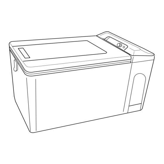
Page 7: Part Name
3. PART NAME ■ MT17F / MT27F DOOR ASSY DIAL HINGE ( long pin ) HINGE, DIAL SIDE (short pin) (Removable door) BASKET HINGE, DIAL SIDE ( long pin ) ( Non-removable door ) COVER ASSY CONTROL ASSY EVA. THERMISTOR (EVAPORATOR THERMISTOR) COOLING UNIT ( K3 ) -
Page 8: Connecting Diagram
4. CONNECTING DIAGRAM ● Block Diagrams ● Wiring Diagrams... -
Page 9: Trouble Shooting
5. TROUBLE SHOOTING Checking Test result Judge Fixing Output Power supply output voltage. Replace the Lower than AC13V Approx. AC13V - 17V ※1 maladjustment power supply. See page 10 Normal 【Check 2】 ■ Does not get Cold The compressor is locked, or Higher than 2.0A contaminated. -
Page 10: Cooling Is Weak
5. TROUBLE SHOOTING Checking Test result Judge Fixing ■ Cooling is Weak Ambient temperature is Please keep the ambient Ambient temparature is higher than 30℃ temperature below 30℃. too high. Make at least 150mm Is the machine part ventilated enough? Insufficient ventilation. -
Page 11: Refrigerator Is Too Cold
5. TROUBLE SHOOTING Checking Test result Judge Fixing ■ Refrigerator is too Cold. (Can not be temperature adjustment) See page11 【Check 4】 Replace the Resistance of the thermistor. Thermistor is broken. ∞Ω thermistor. Approx. 2kΩ - 10kΩ ※2 Normal See page 11 ※2 Ambient temp 25℃... -
Page 12: Typical Problem
5. TROUBLE SHOOTING ■ Typical Problem ※1 Ambient temp 25℃ ※2 Ambient temp 25℃ to -16℃ Symptoms Cause Test Result Treatment Resistance of compressor coil is ∞Ω Coil of the compressor is open Replace the cooling unit Inside of the fridge does not ・Normal: Approx. -
Page 13: Check Point & Check Method
6. CHECK POINT & CHECK METHOD 【Check 1】 Special Fuse & Blade Fuse. (Fig.1) Fig.1 DC CORD ◇ Check the resistance of special fuse by tester. Test result Judge 0Ω Normal ∞Ω Broken SPECIAL FUSE WORK TIPS ・Please attach attention to the special fuse of orientation. -
Page 14: Check 4】 Resistance Of Thermistor
6. CHECK POINT & CHECK METHOD 【Check 4】 Resistance of Thermistor. (Fig.4) POWER SUPPLY Fig.4 ◇ Checking points Remove the two pin couplers from power supply, and test. Test result Judge Approx. 2 kΩ - 10 kΩ Normal ∞Ω Broken 0Ω... -
Page 15: Check 7】 Resistance Of Thermistor
6. CHECK POINT & CHECK METHOD 【Check 7】 Resistance of Thermistor. (Fig.7) ・Please be careful not to mistake the polarity ◇Checking point of the power supply. If want to check the start-up of the fan motor directly, ・When connect with DC24V or wrong polarity, fan motor will fail. -
Page 16: Replacing Parts
7. REPLACING PARTS 【How to Replace Cooling Unit 】 Fig.1 1. Remove the door (Fig.1) DOOR Remove four screws which hold hinges. (Fig.1-①) ① 2. Remove two screws which motor cover. (Fig.2-①) Fig.2 MOTOR COVER Remove the motor cover. (Fig.2-②) ② Cut off the fastener. - Page 17 7. REPLACING PARTS 6. Take out cover pipe and heat insulator. (Fig.6-①) Fig.6 ① COVER PIPE HEAT INSULATOR 7. Remove two screws at the plate of the compressor Fig.7 (Fig.7-①) ① 8. Remove two screws at the plate of the cabinet. Fig.8 (Fig.8-①) ①...
-
Page 18: How To Replace Power Supply
7. REPLACING PARTS 【How to Replace Power Supply】 Fig.11 1. Remove the power supply. 【How to Replace Cooling Unit 】 STEP 1to 5 ② Remove the four screws of power supply. (Fig.11-①) Remove the screw of Earth code. (Fig.11-②) ① ①...
Need help?
Do you have a question about the Engel MT17F-U1 and is the answer not in the manual?
Questions and answers