Advertisement
Quick Links
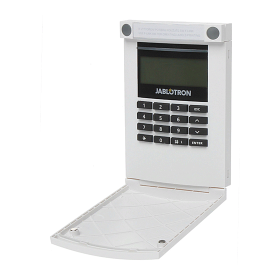
The JA-154E Wireless access module with LCD, RFID and keypad
The JA-154E wireless access module with LCD, RFID and
keypad is a component
of the JABLOTRON 100 system. Its modular
architecture enables users to create a combination whose size of
installation perfectly meets their needs. The device should be installed
by a trained technician with a valid certificate issued by an authorised
distributor.
The wireless access module comprises the keypad (5), RFID
card / tag reader (5), LCD display (4) and the first control
segment (1). JA-192E segments can be used to extend the
JA-154E unit by the required number of segments (the max.
allowed amount is 20 on one unit). The keypad cover (7) can be
removed if the user prefers for full permanent access.
Figure: 1 – control segment; 2 – segment buttons; 3 – backlit activation
button; 4 – LCD display; 5 – access module with RFID card reader; 6 – tabs
for module opening; 7 – keypad cover screws
Figure: 8 – control segment connector; 9 – production code; 10 – terminals;
11 – mini USB connector; 12 – batteries; 13 – tamper contact
Installation
1. Press the four tabs (6) on the sides (see 1st figure) one by one
and release the keypad from the plastic base.
2. When installing more control segments, first remove the socket
st
cover on the 1
segment.
3. Remove the plastic windows from the segments (by levering on
both sides of the segment near the buttons).
4. Always connect the segment wires to the connector of the
previous segment and click them into each other (we recommend
The JA-154E wireless access module with LCD, RFID and keypad
All manuals and user guides at all-guides.com
coiling the wires by turning the segment by 360° - this will prevent
any possible damage to the wires between the plastic parts). Use
this method to install all the required control segments. Finally
push the socket cover in.
5. Insert four 1.5V alkaline AA batteries into the keypad.
6. Attach the base onto the selected place together with the
segments using screws. If multiple control segments are
required attach them onto the wall using screws as well (use
the number of screws required).
7. Connect the segment wires to the internal connector of the
keypad (8).
8. Insert the keypad into the base.
9. Proceed according to the control panel installation manual.
Basic procedure:
a. There must be a JA-110R radio module installed in the
control panel with a reliable communication range to the
keypad.
b. When batteries are inserted, the yellow LED starts to light
permanently which indicates that the keypad has not been
enrolled to the system yet.
c. Go to the F-Link software, select the required position in
the Devices window and launch enrollment mode by
clicking on the Enroll option.
d. Press the backlit activation button (3) – the keypad is thus
enrolled and the yellow LED indicator goes off. (This can
take a few sec.). An enrollment signal can also be sent by
inserting the batteries.
10. When you have completed installation, insert descriptive labels
behind the segment plastic windows and close them. Label
printing is a part of the F-Link software (Devices window, at the
keypad position – Internal settings), or you can use the label
printer.
Note:
Enrolling the module to the system is possible by entering the production
code (9) via F-Link software or by a production code reader. All digits under
the production code are required (1400-00-0000-0001).
1
ABCD...123
Figure: Insertion of a label into a control segment
Setting the properties
Go to the Devices window in the F-Link software. When you are at
the keypad position, use the Internal settings option. The particular
unit is displayed and it is possible to set its properties. It is possible to
assign the required functions to individual segments (controlling of
sections, section status signalling, alarm triggering, PG output
control, PG output status signalling, etc.). More details are available
in the F-Link software.
A common segment (up to 2 of them allowed on one keyboard)
simulates the simultaneous pressing of several segments which are
placed on this keyboard and which control sections. The selection of
sections which are assigned to the common segment is performed by
F-Link SW, the Devices window. At the keyboard position select
Internal settings / and Common segment 1 (2) and mark the segments
which will be operated en bloc. The selected sections will be set / unset
after pressing a button on the common segment. If the states of the
segments which are operated by the common segment are mixed, then
only the segments that need changing will be set / unset. If partial
setting is enabled for some segments, then the common segment
respects this: 1 st. press = partially setting, 2nd press = full setting. It is
not suitable to combine a common segment with a common section
The indication of the common segment is: all segments set = green,
some set (partially set) = yellow, all sections fully set = red.
1 / 2
2
3
4
MLU56204
Advertisement

Related Manuals for jablotron JA-154E


Summary of Contents for jablotron JA-154E
- Page 1 All manuals and user guides at all-guides.com The JA-154E Wireless access module with LCD, RFID and keypad The JA-154E wireless access module with LCD, RFID and coiling the wires by turning the segment by 360° - this will prevent keypad is a component any possible damage to the wires between the plastic parts).
- Page 2 All manuals and user guides at all-guides.com The JA-154E Wireless access module with LCD, RFID and keypad the USB straight to the PC, connection via a USB HUB can Automatically shutting down the module reduce the reliability. The module saves its energy by shutting down the optical 7.
Need help?
Do you have a question about the JA-154E and is the answer not in the manual?
Questions and answers