Advertisement
Quick Links
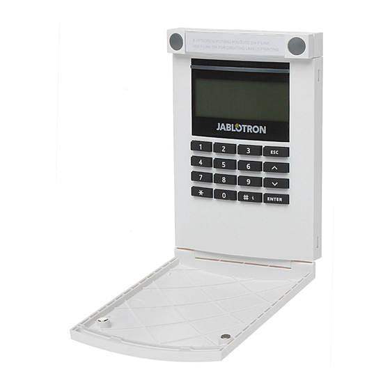
The JA-154E Wireless access module with LCD, RFID and keypad
The access module is a component of the JABLOTRON 100 system.
Its modular architecture enables users to create a combination whose
size of installation perfectly meets their needs. The device should be
installed by a trained technician with a valid certificate issued by an
authorised distributor.
The wireless access module comprises first control segment (1),
an LCD display (4), the keypad and RFID chip card / tag reader (5).
The JA-192E segments can be used to extend the JA-154E unit by the
required number of segments (the max. allowed amount is 20 on one
unit). The tilting keypad cover (7) can be removed if the user prefers
permanent access. It also works as an RFID card / tag reader.
Figure 1: 1 – control segment; 2 – segment buttons; 3 – backlit activation
button; 4 – LCD; 5 – access module with RFID reader; 6 – tabs for module
opening; 7 – cover screws
Installation
1.
Press the four tabs (6) on the sides (see figure 1) one by one and
release the module from the plastic base.
2.
When installing more control segments, first remove the socket cover on
st
the 1
segment.
3.
Remove the transparent plastic cover from the segments (by levering
on both sides of the segment near the buttons).
4.
Always connect the segment wires to the connector of the previous
segment and click them into each other (we recommend coiling the wires
by turning the segment by 360° - this will prevent any possible damage to
the wires between the plastic parts). Use this method to install all the
required segments. Finally push the socket cover in.
5.
Insert four 1.5 V alkaline AA batteries into the module.
6.
Attach the base onto the selected place together with the segments
using screws. If multiple control segments are required attach them onto
the wall using screws as well (use the number of screws required).
7.
Insert the module into the base.
8.
Proceed according to the control panel installation manual. Basic
procedure:
a.
There must be a JA-110R radio module installed in the control
panel with a reliable communication range to the access module.
b.
When batteries are inserted, the yellow backlit activation button (3)
starts to light permanently which indicates that the module has not
been enrolled to the system yet.
c.
Go to the F-Link software, select the required position in the
Devices window and launch enrollment mode by clicking on the
Enroll option.
d.
Press the backlit activation button (3) – the module is thus enrolled
and the yellow LED indicator goes off (this can take a few sec). An
enrollment signal can also be sent by inserting the batteries.
9.
When you have completed installation, insert descriptive labels behind
the segment transparent covers and close them, see figure 3. Label
printing is a part of the F-Link software (Devices window, at the module
position – Internal settings).
Notes:
The module can also be enrolled to the system by entering its
production code (9) in the F-Link software or using a bar code scanner.
All numbers stated under the bar code shall be entered (1400-00-0000-
0001).
To comply with the EN 50131-3 norm it is necessary to fix the cover
tabs (6) by the screws from the accessories. In figure no 1 the cover
tabs are displayed and marked by the arrows.
The JA-154E wireless access module with LCD, RFID and keypad
Figure 2: 8 – connector for control
segments; 9 – production code;
10 – terminals; 11 – mini USB
connector; 12 – batteries;
13 – tamper contact
1
Figure 3: Insertion of a label into a control segment
Setting the properties
Go to the Devices window in the F-Link software. When you are at the
module position, use the Internal settings option. The particular unit is
displayed and it is possible to set its properties. Internal settings is
separated into 2 basic tabs: Segments and Settings.
It is possible to set the required functions for individual segments (control
of sections, section status signalling, alarm triggering, PG output control, PG
output status signalling, etc.).
Common segment – settings and function description
A common segment (up to 2 of them allowed on one module unit)
simulates the simultaneous pressing of several segments which are placed
on this module and which control sections. In the F-Link SW – go to the
Devices tab at the keypad position, Segments tab and select the specific
segment function called Common segment A (B). Then in the new tab
Common segment, select the segments which will be operated en bloc.
Note: A module has to be equipped with a minimum of 3 segments
otherwise this function can not be used.
The selected sections will all be set / unset after pressing a button on the
common segment.
If the states of the segments which are operated by the common segment
are mixed, then only the segments that need changing will be set / unset.
If partial setting is enabled for some segments, then the common segment
st
respects this: 1
press = partially setting, 2
suitable to combine a common segment with a common section.
The indication of the common segment is: all segments unset = green,
some set (partially set) = yellow, all sections fully set = red.
In the Settings tab you can set all other module functions like acoustic
signalling, backlight intensity, RFID reader mode, optical and acoustic
indication, LCD display settings, etc. Details related to settings can be found
in the installation manual of the control panel and of course in the tooltips
displayed by the F-Link software.
Battery power save mode
The module saves its energy by shutting down the optical indication of
system status, the backlit of the LCD display and the RFID reader after 8 sec
when the button, segment or keypad cover have been pressed. The module
still keeps communication with the control panel and it can signal for
example: an entrance delay. Complete waking up is done when you press
the cover of the module, or by pressing of any button.
Alternative power
The module can be powered from an external 12 V DC power supply
via the PWR and GND terminals. The DE 06-12 power supply can be
used. It has the advantage of hidden installation. It permanently
communicates with the control panel and it indicates the system status
according to the Devices / Internal settings. Leave the batteries inside
the module during alternative powering. When the mains power is cut
off, the module will work from the batteries. Inserted batteries are not
charged by the external power supply.
Connection of an external door detector
The module has an input terminal for external door detector
connection. The input (IN) reacts to disconnection from the common
ground. The reaction of this input is programmable by the F-Link SW.
The input has a status reaction.
1 / 2
2
ABCD...123
3
4
nd
press = full setting. It is not
MLU56213
Advertisement

Related Manuals for jablotron JA-154E


Summary of Contents for jablotron JA-154E
- Page 1 The wireless access module comprises first control segment (1), an LCD display (4), the keypad and RFID chip card / tag reader (5). The JA-192E segments can be used to extend the JA-154E unit by the required number of segments (the max. allowed amount is 20 on one unit).
- Page 2 The JA-154E Wireless access module with LCD, RFID and keypad panel or any other device. You can use the cable from the JA-190T card reader. Caution: We strictly recommend connecting the USB cable straight to the PC, connection via a USB HUB can reduce the reliability).
Need help?
Do you have a question about the JA-154E and is the answer not in the manual?
Questions and answers