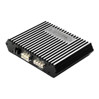
Summary of Contents for Power Acoustik LT1920
- Page 1 Owner’s manual L T-Series LT480/2, LT620/2, LT980/2, LT1440/2 LT1920/2, LT720/4, LT960/4...
-
Page 2: Top Panel Controls
INTRODUCTION Amplifier provide high-performance sound reinforcement for you mobile audio equipment. It’s versatility enables compatibility with optional Equalizers, Frequency Dividing Network Crossovers, and other audio processors in a customized system. The Multi-Mode bridging capabilities allow flexibility in hosting several different speaker configurations. To achieve optimum performance, it is highly recommended that you read this Owners Manual defore beginning installation. -
Page 3: Planning Your System
PLANNING YOUR SYSTEM Before beginning the installation, consider the following: a. If you plan to expand your system by adding other components somrtime in the future, ensure adequate space is left, and cooling requirements are met. b. Should you use high or low inputs? Your Amplifier has been designed to accept either High-Level (speaker outputs from your radio) or Low-Level (Pre-Amp outputs from your radio) signal source. -
Page 4: Wiring Connections
IF YOUR RADIO DOES NOT HAVE +12 VOLT OUTPUT LEAD WHEN THE RADIO IS TURNED ON, THE “REM” TERMINAL ON THE AMPLIFIER CAN BE CONNECTED TO VEHICLE’S ACCESSORY CIRCUIT THAT IS LIVE WHEN THE KEY IS “ON”. MOEDL: LT480/2, LT620/2, LT980/2, LT1440/2, LT1920/2 MOEDL: LT720/4, LT960/4 LT980/2,1440/2.1920/2... -
Page 5: Power Indicator Led
B. VARIABLE LOW-PASS FILTER (30Hz-500Hz) For use as a dedicated subwoofer channel, set filter switch to “LPF”. Adjust variable crossover frequency with control as desired. The amplifier input circuit filters out everything above 30Hz- 500Hz (dependent on the adjustment of the frequency control), so only the deepest bass notes are amplified. - Page 6 If distortion is immediately heard, turn control to “MIN” until the sound is clear. NOTE: NOT PERFORMING ABOVE ADJUSTMENT PROCEDURE AND/OR SIMPLY SETTING THIS CONTROL AT OR NEAR “MAX” POSITION, MAY INDUCE ELECTRICAL AUDIO NOISE INTO THE SYSTEM. MODEL: LT480/2, LT620/2, LT980/2, LT1440/2, LT1920/2 MODEL: LT720/4, LT960/4 Fig 2...
-
Page 7: Connecting The Speakers
CONNECTING THE SPEAKERS MODEL: LT480/2, LT620/2, LT980/2, LT1440/2, LT1920/2 (A) STEREO MODE (B) MONO MODE... - Page 8 (C) TRI MODE TRI MODE OPEATIONAL OUTPUT allows a Crossover (Subwoofer) to be operated in MONO mode while the main speakera are playing in Stereo. Leave the Crossover (Subwoofer) switch on “Full” position. Use a 100 Volt, non-polar capacitor for a high pass crossover and a wire coil (inductor) to block high frequencies from the Crossover (Subwoofer) as shown in the figure below.
- Page 9 Model: LT720/4, LT960/4 (A) 4 CHANNEL MODE (B) 3 CHANNEL MODE (C) 2 CHANNEL MODE...
- Page 10 (D) 6 CHANNEL MODE COMPONENT VALUES FOR 6dB PASSIVE CROSSOVER FREQUENCY 80 Hz 100 Hz 120 Hz 150 Hz INDUCTOR CAPACITOR 7.5 mH 470 uF 6.5 mH 330 uF 330 uF 5.5 mH 4 mH 220 uF...
-
Page 11: Troubleshooting Guide
TROUBLE SHOOTING GUIDE SYMPTOMS CHECK POINTS In the power NO SOUND METER LAMP illuminated? Is the Diagnosic LED illuminated? AMP NOT No power to power wire SWITCHING No power to remote wire with receiver on Fuse broken NO SOUND Check Speaker Leads IN ONE CHANNEL Check Audio Leads... - Page 12 WARNING Investigate the layour of you automobile thoroughly before drilling or cutting any holes. Take care when you work near the thanks, lines, or hydraulic lines, and electrical wiring. Don’t mount this system so that the wire connections ate unprotected are subjectto pinching or damage from nearby objects.


Need help?
Do you have a question about the LT1920 and is the answer not in the manual?
Questions and answers