Table of Contents
Advertisement
Quick Links
Analyze
Detect
Measure
Control
•
•
•
Orion Low-Level
Chloride Monitor
I N S T R U C T I O N M A N U A L
™
test
sample
values
values
˚C
ppm
mV
ppb
slope
error
E
stable
0
enter /
done
test
sample
program
cal
three
pt. cal.
point 1
cal.
complete
cal
cal
point 2
point 3
error
PURE WATER
TM
Monitors
Orion 1800
series
release latches to access
Orion 1817LL
Advertisement
Table of Contents

Related Manuals for Thermo Electron PURE WATER Orion 1817LL


Summary of Contents for Thermo Electron PURE WATER Orion 1817LL
- Page 1 Orion 1817LL Orion Low-Level Chloride Monitor I N S T R U C T I O N M A N U A L test sample values values ˚C slope error stable enter / done test sample program three pt. cal. point 1 cal.
- Page 2 ORION ORP Standard is protected by US Patent 6,350,367. ORION Series A conductivity meters are protected by US Patent 5,872,454. © Copyright 2003, Thermo Electron Corporation. All rights reserved. Question everything, and Analyze. Detect. Measure. Control are trademarks of Thermo Electron Corporation.
-
Page 3: Table Of Contents
TABLE OF CONTENTS General Information Calibration Introduction Three-Point Calibration Procedure Principles of Operation One-Point Calibration Procedure Principles of Calibration Off-line Calibration Procedure Sample Requirements VI. Instrument Maintenance Description of Orion 1817LL Monitor Weekly Maintenance Instrument Preparation Monthly Maintenance Unpacking Orion 1817LL and Cooler Bi-Monthly Maintenance Mounting, Plumbing and Wiring of Yearly Preventive Maintenance... -
Page 5: General Information
I. GENERAL INFORMATION Introduction Principles of Operation This manual covers the operation, maintenance and Figure 1 is a block diagram of sample flow through troubleshooting for the Orion 1817LL which the monitor. Figure 2 illustrates the sample flow incorporates the software features of a three point and during normal operation. -
Page 6: Principles Of Calibration
Principles of Calibration Response of the Low-Level Chloride Electrode The U.S. patented chloride electrode responds to Calibration procedures for analytical instruments are changes in chloride ion concentration. This response important and must be performed carefully. The Orion is described as follows: 1817LL employs a two-segment calibration method to cover a wide range of concentrations, the first The sensing surface of the electrode consists of the... -
Page 7: Sample Requirements
Pressure — 8 - 100 psig. Consult Thermo Electron for the previously stored reading is adjusted to the lab details on sample handling if pressure is method result;... -
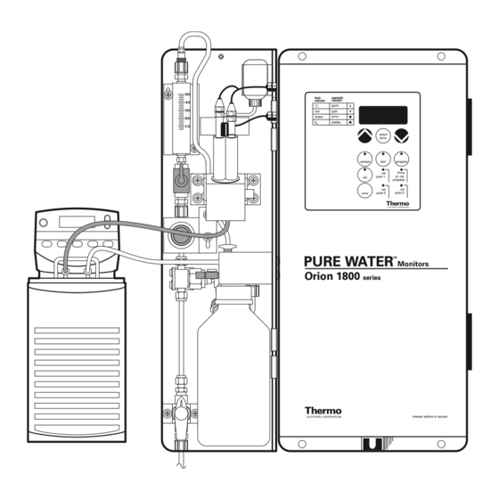
Page 8: Description Of Orion 1817Ll Monitor
Description of Orion 1817LL NOTE: Numbers in the description refer to Figure 3. Sample Inlet Valve (1) — Accepts the sample stream LED Display (17) — Provides digital readouts of via 1/4 inch NPTF connector. The customer must concentration, temperature, millivolts and error codes. supply the sample with a pressure between 8 and Keypad (18) —... - Page 9 test sample values values ˚C slope error stable enter / done sample test program three pt. cal. point 1 cal. complete point 2 point 3 error PURE WATER Monitors Orion 1800 series release latches to access Figure 3: Major Components of Low-Level Chloride Monitor...
-
Page 11: Instrument Preparation
II. INSTRUMENT PREPARATION Unpacking Orion 1817LL Report any obvious damage of shipping container to carrier and hold for inspection. The carrier (not Thermo Electron) is responsible for any damage incurred during shipment. 1. Open outer box. Remove foam corner support pieces. - Page 12 Mounting And Plumbing Instructions Electrical Connection Instructions 1. Select a site for the instrument that allows it to be 1. Remove the protective plastic, front panel inside permanently bolted (in an upright position) with the cabinet by unscrewing the 4 holding screws. ample height for atmospheric drain operation and Remove the protective plastic plug at the bottom ready access to to both electronic controls.
- Page 13 Cooler Connection Instructions 1. Open the bag which contains the tubing 11. Push the free end of the foam insulation back, components. The bag should contain 10 feet of exposing about two inches of plastic tubing. 1/4” plastic tubing, 5 feet of foam tubing insulation, Remove the smaller nut from one of the union and two 1/4-3/8 union compression fittings.
-
Page 14: Installation Of Reagent And Diffusion Tubing
Installation Of Reagent And Diffusion View Front Left Side of Analyzer Tubing WARNING: Formic acid is hazardous. Use Injection Port protective glasses and gloves. Refer to bottle label for precautions. fluid connector block 1. Support the bottom of the reagent bottle. Turn thumbscrew, counterclockwise to release diffusion bottle. -
Page 15: Installation Of Reference Electrode
Installation of Reference Electrode 1. Unpack reference electrode, 7, (Orion 100057) and tubing from shipping box. Remove protective caps from bottom and sidearm of electrode. Save caps for future storage of electrode. Inspect internal of electrode (item 7 in Figure 8). Verify it is at least half filled with the internal fill solution. -
Page 17: Instrument Operation
III. INSTRUMENT OPERATION Description of Basic Unit Controls On/off switch - Controls power to all electronics and air pump. It is located on electronic chassis bottom test sample values values and includes an integral circuit breaker. ˚C LCD display - Displays four-and-one-half digit plus polarity sign used to read concentration, slope, E error slope... -
Page 18: Initial Instrument Set-Up
Initial Instrument Set-Up Use of Test Mode Before first sample measurements on Orion 1817LL When test key is pressed, the LCD displays can be performed, calibration concentration temperature, millivolts, high range, slope and E increments must be programmed into memory. See Every time the test key is pressed the monitor steps Table 1 below. -
Page 19: Error Mode
Error Mode The Orion 1817LL Monitor diagnoses two types of Table 2 errors which are termed “hard” and “soft.” In the event Error of hard error, the analyzer cannot compute any Code Meaning meaningful concentration values, error LED will be lit and LCD will display an error code. -
Page 20: Shutdown And Start-Up Procedure
Shutdown And Start-Up Procedure Start-up 1. Replace the diffusion tubing if sample flow has The following steps should be taken if a loss of sample been off for more than a few days. Tubing flow is expected for more than one day. These becomes brittle with long term exposure to procedures will prevent possible build-up of acidic reagent. -
Page 21: Instrument And Operation Of Modules
IV. INSTALLATION AND OPERATION OF MODULES Signal Conditioner Module (Orion 180001) The Orion 1817LL Monitor is shipped with signal conditioner module (Orion 180001) factory installed. Read section Setting Module Output and if you need to change the factory settings, see Removing Installed Module. -
Page 22: Electrical Connections
Electrical Connections Description Of Signal Conditioner 1. If module keypad is still attached, then unscrew Set zero — Sets lower level concentration output. In module keypad from black brackets using the two this mode LED above set zero is active. To set output screws on the keypad. -
Page 23: Programming Measuring Range
Programming Measuring Range 1. Press set zero key. LED above set zero will Table 5 activate and LCD will display current programmed Default Values — Orion 1817LL value. Preset default value is 0.1 ppb for log range P0 Off-line CAL Value and 0.1 ppb for linear range. -
Page 24: Optional Alarm Module
Optional Alarm Module Setting Alarm Output (Orion 180011) The Orion 1817LL alarm circuit is unique. If the For both alarms 1 and 2, NO and NC conditions are instrument detects chloride concentration is increasing available simultaneously. For “alarms disabled” at such a rate that high alarm value will be reached condition, either NO (factory set) or NC is available. -
Page 25: Electrical Connections For Alarm Module
Electrical Connections for Alarm Module Description of Alarm Module Controls 1. Feed wire through hole in chassis bottom. Set alarm 1 — Sets alarm 1 parameter. When set alarm 1 is pressed, LED on key is active. See Table 5 2. -
Page 26: Alarm During Calibration
Alarm During Calibration During calibration the alarm module is automatically deactivated. After the completion of calibration the Series 1800 Monitor automatically enters the sample mode, however, the alarm module remains deactivated. To reactivate, press sample key. The alarm module is deactivated to avoid the high concentration alarm that would result from the standards used to calibrate. -
Page 27: Calibration
V. CALIBRATION Note: Sample flow rate must be maintained c. Press the program key until the value of P3 is displayed. Press the ▲ and ▼ keys, if required, at 40 mL/min during calibration. to change the value to the desired standard 3 concentration value then press the enter/done Procedure for 3-Point Calibration: key to accept the new value. -
Page 28: Three-Point Calibration Procedure
Off-Line Calibration Procedure The off-line calibration feature is simply a one-point throughout the procedure. Also, the zero chloride calibration, using an alternate method value for P0. solution can be used for convenience. A known The term “off-line calibration” refers only to the fact chloride concentration can also be generated by using that a sample from Orion 1817LL bypass is taken “off- the calibrator and the zero chloride solution. -
Page 29: Instrument Maintenance
Electron Service Department, and is especially useful to plants who rotate Monthly Maintenance instrument operators. Thermo Electron’s Service Department provides a Polish Chloride Electrode Using Orion 151713 periodic checkout, calibration, and operator training Chloride electrode should be polished according to service on site to certify analyzer performance to instructions on Polishing Strips (Orion 151713). -
Page 30: Bi-Monthly Maintenance
Bi-Monthly Maintenance Replacement/Cleaning of Sample Inlet Filter Replacement of Reagent, Tubing and O-rings 1. Turn off sample flow. 1. Replace acid reagent and diffusion tubing. Shut off analyzer prior to inlet. Remove reagent diffusion 2. Remove filter hex cap using 1-inch open-ended bottle by unscrewing the black thumbscrew at top of wrench. -
Page 31: Yearly Preventive Maintenance
Yearly Preventive Maintenance Replace Reference Electrode (Orion 100057) restrictor tube assembly 1. See Instrument Preparation for step-by-step instructions. restrictor Replace Sensing Electrode (Orion 100025) adapter 1. See Instrument Preparation for step-by-step instructions. fitting Reagent Bottle Assembly O-Ring 1. When reagent bottle is removed, replace O-ring clamp between bottle and adaptor. -
Page 32: Troubleshooting
VII. TROUBLESHOOTING The following section covers troubleshooting that can be In the U.S., Thermo Electron Customer Support can be performed without special tools or skills. Note that in consulted for troubleshooting advice at most installations, the temperature in the flow cell 1-800-225-1480 except within Massachusetts, call should read between 0 - 15 ˚C, millivolt reading... - Page 33 Electrode failure Replace one or both electrodes Temperature probe failure Replace or consult Thermo Electron Electronics failure Try resetting computer, or consult Thermo Electron Inaccurate Standards or Use new standard solution, check...
- Page 34 Default Power loss while back-up battery Allow battery to charge overnight. was not fully charged Recalibrate and reprogram Battery failure Consult Thermo Electron Electronics failure Try resetting computer, or consult Thermo Electron Incorrect Keyboard Display Computer glitch Turn main power off and on.
-
Page 35: Repair And Service
VIII. REPAIR AND SERVICE For the most current warranty information, visit www.thermo.com. After troubleshooting all components of your measurement system, contact The Technical Edge for Orion products. Within the United States call 1.800.225.1480, outside the United States call 978.232.6000 or fax 978.232.6031. In Europe, the Middle East and Africa, contact your local authorized dealer. -
Page 37: Notice Of Compliance
IX. NOTICE OF COMPLIANCE This meter may generate radio frequency energy and If necessary, the user should consult the dealer or an if not installed and used properly, that is, in strict experienced radio/television technician for additional accordance with the manufacturer’s instructions, may suggestions. -
Page 39: Declaration Of Conformity
X. CERTIFICATE OF CONFORMITY Manufacturer: Thermo Electron Corporation 166 Cummings Center Beverly, MA 01915 Hereby declares that the products 1809AO Fluoride Monitor 1810A0 Ammonia Monitor 1811A0 Cation Sodium Monitor 1811EL Low-Level Sodium Monitor 1817LL Low-Level Chloride Monitor 1817HL High-Level Chloride Monitor... -
Page 41: Warranty
Industrial products used at nuclear facilities are accident, alteration, misuse, or abuse. also subject to Thermo Electron nuclear terms and conditions. Contact Thermo Electron if you do not In the event of failure within the warranty period, have a copy. -
Page 43: Ordering Information
XII. ORDERING INFORMATION Consumables Orion Description Orion Description 1817LL Microprocessor Low-Level Chloride 181060 Diffusing tubing (four 2 ft. lengths). Analyzer with cooler, 115 V, complete 182011* Acid Reagent for 60 days operation with chloride electrode (Orion 100025), (one liter bottle) with one 2 foot reference electrode (Orion 100057), length thin-walled tubing and temperature sensor (Orion 181127),... - Page 44 For Three Point Calibration Spare Parts Orion Description Orion Description 15DC15/15DC20 Dynamic calibrator for use with 201815-001 Standard injection port. multiple instruments. Includes 204743-001 Power switch. syringe kits (Orion 150096 and 180096) and mounting bracket. 217135-A01 Connector block assembly with thumb screw and injection port.
-
Page 45: Appendix
XIII. APPENDIX Resetting Monitor Resetting the monitor will clear any erroneous values 1. Turn power to analyzer OFF. that have been stored in memory. Resetting will also 2. Loosen the four screws holding keypad and let it set all values back to the default values. The default hang loose by its ribbon cable. -
Page 46: Mounting Dimensions
Mounting Dimensions NOTE: Three Point Calibration — If dynamic calibrator and optional mounting shelf are used, leave 12” clearance beneath analyzer. FRONT SIDE .375" DIA. 15.00" VIEW VIEW 6.50" 24.75" 22.75" 23.50" 26.00" 3.00" 10.50" 0.125" 7.00" 1.53" 26.67 cm 0.318 cm 10.06"... -
Page 47: Mounting Recommendation And Dimensions
Mounting Recommendation and Dimensions Monitor Sampler 7" ref. test sample values values ˚C slope error stable enter / done sample test program three point 1 pt. cal. " ref. cal. complete point 2 point 3 error QC Sampler pressure flow rate release valve adjustment 105974... -
Page 48: Qc Sampler Installation And Operational Procedure
XIV. ORION QC SAMPLER INSTALLATION AND OPERATIONAL PROCEDURE Introduction 9. Shut of the valve, 6, to stop sample flow through the monitor. The QC Sampler is a portable unit that connects to an 1800 Series monitor to provide for rapid verification of Note: this valve is lower than pictured on samples or standards. -
Page 49: Specifications Of Orion 1817Ll
XV. SPECIFICATIONS OF ORION 1817LL Measuring Range Sample Outlet 5 ppb to 10 ppm chloride. 3/4” NPT-male Display Calibration Four and one half LCD digits for concentration, slope, Three-point, off-line calibration, blank correction. zero-potential, mV, temperature, error codes and Flow diagnostic information. -
Page 50: Specifications Of Qc Sampler
XVI. SPECIFICATIONS OF QC SAMPLER Product Performance Specification: Environmental Conditions: Electrical Requirements: Temperature: 24 V DC, 50/60 Hz, 100 watts 5-45 °C Input: Humidity: 110 VAC Adapter 95% Relative Maximum, non-condensing. Flow Rate: 40 mL/min nominal set by pressure regulator. Compatibility: All Orion 1800 Series Monitors. - Page 51 Environmental Instruments Water Analysis North America 166 Cummings Center Beverly, MA 01915 USA Tel: 978-232-6000 Dom. Fax: 978-232-6015 Int’l. Fax: 978-232-6031 Europe 12-16 Sedgeway Business Park Witchford, Cambridgeshire England, CB6 2HY Tel: 44-1353-666111 Fax: 44-1353-666001 Far East Room 1205 China Resources Bldg. 26 Harbour Road Wanchai, Hong Kong Tel: 852-2885-4613...
Need help?
Do you have a question about the PURE WATER Orion 1817LL and is the answer not in the manual?
Questions and answers