
Subscribe to Our Youtube Channel
Related Manuals for Thermo Electron Polysonics SX40


Summary of Contents for Thermo Electron Polysonics SX40
- Page 1 Polysonics SX40 Dedicated Doppler Flowmeter User Guide P/N 1-0563-006 Revision G HDS MESSTECHNIK Franz-Kissing-Straße 7 58706 Menden Tel.: 02373 / 1341 Fax: 02373 / 2488 info@hds-messtechnik.de www.hds-messtechnik.de Analyze · Detect · Measure · Control...
- Page 2 Polysonics SX40 Dedicated Doppler Flowmeter User Guide P/N 1-0563-006 Revision G...
- Page 4 All other trademarks are the property of Thermo Electron Corporation and its subsidiaries. Thermo Electron Corporation (Thermo) makes every effort to ensure the accuracy and completeness of this manual. However, we cannot be responsible for errors, omissions, or any loss of data as the result of errors or omissions.
- Page 5 This page intentionally left blank.
-
Page 6: Table Of Contents
HydraScan ..................3-6 Chapter 4 Setup Items ......................4-1 Reset ....................4-1 Config....................4-1 I/O Test ....................4-1 Relays....................4-1 4–20 mA Loop Calibration .............. 4-1 4–20 mA Loop Test ................. 4-2 Flow....................4-2 Rate....................4-2 Thermo Electron Corporation Polysonics SX40 User Guide... - Page 7 Replacing the 4–20 mA Board ............6-7 Replacing the Fuse ................6-8 Upgrades..................... 6-9 Service & Returns ................6-9 Warranty................... 6-10 Appendix A Hazardous Area Installations ................ A-1 Appendix B Obtaining Pipe ID..................... B-1 iii Polysonics SX40 User Guide Thermo Electron Corporation...
-
Page 8: Chapter 1 Product Overview
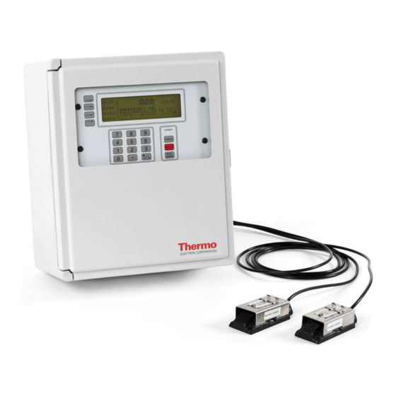
Chapter 1 Product Overview Introduction Thermo’s Polysonics SX40 Dedicated Doppler Flowmeter generates two independent ultrasonic signals at different frequencies. By correlating these frequencies, the instrument automatically identifies and eliminates noise errors from sources such as variable frequency drives. In addition, operation of the instrument is enhanced by an Expert System which allows the flowmeter to automatically “learn”... -
Page 9: Specifications
Two encapsulated dual frequency sensor heads suitable for submersible/underground service Encased in stainless steel shrouds, with stainless steel straps and quick clamps Cable length: 30 ft (9 m) Weight: 12 lb (5.4 kg) Dimensions: Refer to the Figure 1–1 Polysonics SX40 User Guide Thermo Electron Corporation... -
Page 10: Functional
Display: Backlit, 240 x 60 dot, high resolution graphics display Data Logger 90000-point data logger Programmable in intervals of 30 s, 1, 5, 15, 30, and 60 min Programming: Via HydraScan software or integral keypad Serial Interface: RS232 Thermo Electron Corporation Polysonics SX40 User Guide... -
Page 11: Approvals
Optional: CSA Class I, Div. 2 or Class II, Div. 2 Optional: CSA Intrinsically Safe Class I, Div. 1; Class II, Div. 1; or Class III, Div. 1 Optional: Intrinsically Safe CENELEC (LCIE) Polysonics SX40 User Guide Thermo Electron Corporation... -
Page 12: Chapter 2 Installation & Wiring
E: Sediment collects at the bottom of the horizontal pipe ● Note Selecting the proper installation location is essential to flow measurement reliability. Each application is unique and may require a variation of installation locations. ▲ Thermo Electron Corporation Polysonics SX40 User Guide... - Page 13 Figure 2–2. Recommended transducer orientations 3. Attach the transducers to the pipe strap: a. Use a screwdriver to loosen the mounting screw and slide the lock back on each transducer. Figure 2–3. Polysonics SX40 User Guide Thermo Electron Corporation...
- Page 14 Remove the strap from the pipe, and apply sonic coupling compound to each transducer surface. f. Reposition the strap on the pipe, placing the transducers in the proper positions. Thermo Electron Corporation Polysonics SX40 User Guide...
-
Page 15: Mounting The Enclosure
2. Remove the meter access cover, and locate the 4 mounting holes (1 in each corner of the cover). 3. Attach the enclosure to the wall using the mounting screws. 4. Replace the meter access cover. Note An optional mounting ear package is also available. ▲ Polysonics SX40 User Guide Thermo Electron Corporation... -
Page 16: Wiring
If the input voltage is 220 V, second hot wire to L2/N 6. Turn the terminal screws clockwise to close them connections. 7. Ensure the wires are securely connected to the input block, and replace the meter access cover. Thermo Electron Corporation Polysonics SX40 User Guide... -
Page 17: Dc Power
3. Make the following connections: a. +24VDC to P2 +24 b. 24 VDC return to either of the P2 GND connections 4. Turn the terminal screws clockwise to close them connections. Polysonics SX40 User Guide Thermo Electron Corporation... -
Page 18: Transducers
3. Remove the nut from the transducer cable connector, and draw the cable through the opening in the meter enclosure. 4. Thread the nut onto the cable connector to the inside of the enclosure. Thermo Electron Corporation Polysonics SX40 User Guide... - Page 19 Second braided ground wire to RCV GND 10. Turn each screw clockwise to close the connections. 11. Ensure the wire connections are secure, and replace the meter access cover. Figure 2–9. Transducer cable seal assembly Polysonics SX40 User Guide Thermo Electron Corporation...
-
Page 20: Relays
3. Locate the 4 relay terminals blocks, and select the relay you are going to wire. 4. Locate the Normally Closed (NC), Common (C), and Normally Open (NO) relay contacts on the terminal block. Thermo Electron Corporation Polysonics SX40 User Guide... - Page 21 7. Turn the terminal screws clockwise to close the connections. 8. Ensure the wire connections are secure, and test the relay (see “I/O Test” in Chapter 4). 9. Replace the meter access cover. Figure 2–11. Relay schematic 2-10 Polysonics SX40 User Guide Thermo Electron Corporation...
-
Page 22: Ma Current Loop (Rev. F Or Earlier)
Note These instructions for instruments with main PCB 22302-0002 Rev. F or earlier. ▲ For instructions on performing a 4–20 mA calibration and/or test, refer to “I/O Test” in Chapter 3. 1. Refer to Figures 2–13 and 2–14. Thermo Electron Corporation Polysonics SX40 User Guide 2-11... - Page 23 4. Connect the wiring to the module. 5. Replace the access cover. Figure 2–13. Self-powered current loop & pin configuration Figure 2–14. Externally powered current loop & pin configuration 2-12 Polysonics SX40 User Guide Thermo Electron Corporation...
-
Page 24: Ma Current Loop (Rev. G Or Later)
3. Use jumpers to configure the pins on the 4–20 mA card according to the power option selection. 4. Connect the wiring to the module. 5. Replace the access cover. Thermo Electron Corporation Polysonics SX40 User Guide 2-13... -
Page 25: Connecting A Switch To Remote Zero Feature
Warning Prevent possible electrical shock and/or damage to the meter: Disconnect power to the meter PRIOR TO wiring. ▲ Refer to step 9 in “Manual Mode” (Chapter 3) for instructions on enabling the remote zero function. 1. Refer to Figure 2–17. 2-14 Polysonics SX40 User Guide Thermo Electron Corporation... - Page 26 First switch wire to RLYCOM b. Second switch wire to POSZERO 6. Turn the screws clockwise to close the connections. 7. Ensure the wire connections are secure, and replace the meter access cover. Thermo Electron Corporation Polysonics SX40 User Guide 2-15...
- Page 27 Installation & Wiring Figure 2–17. Remote zero connections 2-16 Polysonics SX40 User Guide Thermo Electron Corporation...
-
Page 28: Chapter 3 Operation & Configuration
2. When the Adjust Contrast screen appears, press the +/- key again, and the software scrolls through the levels of contrast. Press the +/- key to stop the scrolling. 3. Use the scroll and backspace keys to make fine adjustments to the contrast. Thermo Electron Corporation Polysonics SX40 User Guide... -
Page 29: Configuration
Warnings” (Table 6–2 in Chapter 6) if you receive one of the following messages: Invalid Signal, Can’t Learn ● No Flow, Can’t Learn ● Warning Low S Strength ● Warning Poor S Strength ● Polysonics SX40 User Guide Thermo Electron Corporation... -
Page 30: Manual Mode
The damping coefficient suppresses short term fluctuations in the indicated flow rate. Increasing the coefficient increases the response time to changes. Keep damping at a minimum unless the flow rate Thermo Electron Corporation Polysonics SX40 User Guide... - Page 31 Enter the site calibration adjustment. 8. Select Next. At this screen: a. Scroll to the required totalizer unit (US gallons, Imperial gallons, million gallons, cubic feet, cubic meters, liters, oil barrels, liquid barrels) and press Enter. Polysonics SX40 User Guide Thermo Electron Corporation...
- Page 32 Enter the flow rate that equals the 20 mA (maximum) reading, and press Enter. 12. Select Next, and if a password is required, enter it here. 13. Select Next to move to the final setup screen. Thermo Electron Corporation Polysonics SX40 User Guide...
-
Page 33: Hydrascan
14. Set the time and date at this screen, and press Next to complete the configuration process. HydraScan You can also use the HydraScan software to configure the instrument. Refer to the HydraScan user guide (P/N 1-0563-005). Polysonics SX40 User Guide Thermo Electron Corporation... -
Page 34: Chapter 4 Setup Items
For wiring instructions, refer to Chapter 2. 15. Set up a calibration current loop. 16. Access the mA Cal screen, and enter the value in mA from the current meter that corresponds to the zero scale. Thermo Electron Corporation Polysonics SX40 User Guide... -
Page 35: 4-20 Ma Loop Test
The meter records the maximum flow, date, and time of the maximum flow since the last reset. You can view this information from the Max screen. Reset the data by changing the Max field selection from “Set” to “Clear.” Polysonics SX40 User Guide Thermo Electron Corporation... -
Page 36: Flow Menu Items
The meter records the maximum flow, date, and time of the maximum flow since the last reset. You can view this information from the Max screen. Reset the data by changing the Max field selection from “Set” to “Clear.” Thermo Electron Corporation Polysonics SX40 User Guide... - Page 37 This page intentionally left blank.
-
Page 38: Chapter 6 Troubleshooting & Maintenance
4. Restart meter. 1. Turn meter off, and remove the transducers. 2. Grind the pipe surface if it is rough or coated. 3. Remount the transducers. 4. Restart the meter. See if warning clears. Thermo Electron Corporation Polysonics SX40 User Guide... -
Page 39: Learn Mode Warnings
1. Refer to Table 6–1 and complete actions B–D, checking the meter after performing each action to see if the problem was corrected. Signal Status 2. Check the FFT. 3. Contact Thermo. IS – Invalid 1. Check the FFT. Signal 2. Contact Thermo. 6-2 Polysonics SX40 User Guide Thermo Electron Corporation... -
Page 40: Variable Frequency Drives (Vfds)
No Doppler reflection Ultrasound signal not transmitting 1. Refer to Table 6–1 and complete action codes A-D, checking the meter after performing each action to see if the problem was corrected. I or II Thermo Electron Corporation Polysonics SX40 User Guide 6-3... - Page 41 Troubleshooting & Maintenance Figure 6–1. Ideal Doppler shape Figure 6–2. Broadband noise Figure 6–3. Steady noise spike with Doppler Figure 6–4. Fluctuating Doppler profile 6-4 Polysonics SX40 User Guide Thermo Electron Corporation...
-
Page 42: Signal Quality & Strength
Refer to the following figure to determine the quality of the application. Also refer to Table 6–1 for actions you can take to attempt to improve signal quality and strength. Figure 6–7. Thermo Electron Corporation Polysonics SX40 User Guide 6-5... -
Page 43: General
2. Remove the meter access cover. 3. Locate the relay sockets (reference Figure 2–11), and remove the relay. 4. Push the replacement relay into the socket until it is secure. 5. Replace the access cover. 6-6 Polysonics SX40 User Guide Thermo Electron Corporation... -
Page 44: Replacing The 4-20 Ma Board
7. Wire and configure (reference Chapter 2) the 4–20 mA loop. 8. Reconnect power, and calibrate the current loop according to “4–20 mA Loop Calibration” in Chapter 4. 9. Replace the access cover. Thermo Electron Corporation Polysonics SX40 User Guide 6-7... -
Page 45: Replacing The Fuse
3. Insert a similar fuse of the same rating (see Figure 6–9). 4. Replace the fuse holder. Depress and turn the holder clockwise until it locks in place. 5. Replace the access cover if removed. 6-8 Polysonics SX40 User Guide Thermo Electron Corporation... -
Page 46: Upgrades
3. Include a letter fully explaining the symptoms of the failure as well as detail describing the application where the unit was being operated. Also include a contact name, phone number, and purchase order authorizing repairs. Thermo Electron Corporation Polysonics SX40 User Guide 6-9... -
Page 47: Warranty
EXCEPT AS OTHERWISE AGREED TO IN WRITING BY Thermo, THE WARRANTIES GIVEN ABOVE ARE IN LIEU OF ALL OTHER WARRANTIES, EXPRESSED OR IMPLIED, AND Thermo HEREBY DISCLAIMS ALL OTHER WARRANTIES, INCLUDING THOSE OF MERCHANTABILITY AND FITNESS FOR PURPOSE. 6-10 Polysonics SX40 User Guide Thermo Electron Corporation... -
Page 48: Appendix A Hazardous Area Installations
Appendix A Hazardous Area Installations Figure A–1. Hazardous area installation with barriers Thermo Electron Corporation Polysonics SX40 User Guide... - Page 49 Hazardous Area Installations Figure A–2. Hazardous area installation without barriers Polysonics SX40 User Guide Thermo Electron Corporation...
-
Page 50: Appendix B Obtaining Pipe Id
15.255 14.876 14.438 17.250 17.000 20.000 19.634 19.500 19.250 19.000 18.812 18.376 17.938 17.438 17.000 16.500 16.062 19.250 19.000 24.000 23.564 23.500 23.250 22.876 22.624 22.062 21.562 20.938 20.376 19.876 19.312 23.250 23.000 Thermo Electron Corporation Polysonics SX40 User Guide... - Page 51 84.10 All measurements in inches Note For pipes with cement linings, reduce the pipe ID by twice the lining thickness. Standard and double cement lining thicknesses are listed in the next table. ▲ Polysonics SX40 User Guide Thermo Electron Corporation...
- Page 52 49.22 49.08 48.94 57.10 55.96 55.80 55.64 55.48 55.32 55.16 55.00 All measurements in inches Note For pipes with cement linings, reduce the pipe ID by twice the lining thickness listed above. ▲ Thermo Electron Corporation Polysonics SX40 User Guide...
- Page 53 This page intentionally left blank.
Need help?
Do you have a question about the Polysonics SX40 and is the answer not in the manual?
Questions and answers