Table of Contents
Advertisement
Quick Links
Advertisement
Table of Contents

Related Manuals for VOLTA ecoPowerTrolley

Summary of Contents for VOLTA ecoPowerTrolley
- Page 1 Technical Manual BA_ecoPowerTrolley_1.4_en...
- Page 2 +41 41 811 41 42 ecovolta AG info@eco-volta.com Gersauerstrasse 71 eco-volta.com 6440 Brunnen Switzerland This document may not be reproduced without the written permission of ecovolta AG neither reproduced nor otherwise reused. © 2023 ecovolta AG. All rights reserved. Data without guarantee. Subject to change without notice.
-
Page 3: Table Of Contents
Table of contents Table of contents About this content............................1 Validity..............................1 Content and purpose...........................1 Additional information........................1 Change course............................1 Warnings and categories........................1 Getting to know the device...........................2 Intended use............................2 Improper use............................2 Technical features..........................2 Which device variants are available?..................... 2 How is the device constructed?...................... -
Page 4: About This Content
Product Name: ecoPowerTrolley • Content and purpose This information is limited to the assembly, installation, setup and basic operation of the product. Additional information Additional information can be downloaded here: www.ecopowertrolley.com Change course BA_ecoPowerTrolley_1.0: Release • BA_ecoPowerTrolley_1.1: Various adjustments •... -
Page 5: Getting To Know The Device
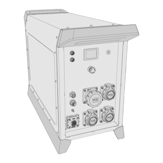
Technical features Due to the specific design of the ecoPowerTrolley, the operation of sensitive loads (e.g. AV devices) as well as the use of devices with strong repercussions on the AC grid (e.g. due to high starting currents or reactive power requirements) does not pose a problem. - Page 6 2 Getting to know the device Controls On/Off button Display/touchscreen (touch screen) Connections Connection for CAN communication Output 24 V DC Connection for charging cable of PV system Connection for parallel connection of max. 2 trolleys (coming soon) Connection for charging cable Connection for external grounding 3 outputs 230 V;...
-
Page 7: Interpret Lables
2 Getting to know the device Interpret lables 2.6.1 Identify the device using the nameplate Find nameplate The nameplate can be found on the frame above the display. Make sure that these operating instructions belong to your device. These operating instructions do not apply to other devices, even if they look similar or appear to be identical. -
Page 8: 2.6.2 Other Markings On The Device
2 Getting to know the device 2.6.2 Other markings on the device Marking of the emergency stop button Symbol for external ground connection Labeling of the on/off button BA_ecoPowerTrolley_1.4_en... -
Page 9: Technical Data
2 Getting to know the device Technical data Physical data B1 Wide 357 mm B2 Wide 540 mm H1 Height 596 mm H2 Height 685 mm T1 Depth 944 mm Weight 80 kg Weight 83 kg Electrical data Outputs 3 sockets (CEE7 / T23): 230 V L + N + PE; 50/60 Hz 1 socket (CEE16): 3 x 400 V 3 L + N + PE;... - Page 10 2 Getting to know the device Derating operation In order to extend the battery life and prevent failures, the device automatically switches to derating mode in extreme operating conditions. In derating mode, the power that can be supplied to the device during charging or withdrawn during operation is limited.
- Page 11 2 Getting to know the device Operation at high ambient temperatures The ecoPowerTrolley dissipates the waste heat generated during operation via cooling fins to the ambient air. Consequently, the attainable cooling capacity is reduced at high ambient temperatures. If the peak power is removed for a short time, this effect is not significant; otherwise, the following limitations arise: When the maximum output power is removed, the attainable running time is reduced.
-
Page 12: Safety First
3 Safety first! Safety first! General and special safety instructions Personnel qualification No special personnel qualification is required to use the device. The device may be used by any • person who is physically and mentally capable of doing so and who has read and understood the operating instructions. - Page 13 3 Safety first! Warning for persons with medical implants Keep away from the device. Electromagnetic radiation is generated • during operation of the device, which may have an effect on medical implants. General safety instructions Do not open the device housing. •...
- Page 14 3 Safety first! Safety during operation (discharging) High voltage and high currents at the voltage outputs. • Danger due to arc fault when disconnecting plugs. Do not disconnect any plugs during discharging operations. Hot cooling fins in operation. • Danger of burns. Do not touch the cooling fins.
-
Page 15: Fire Protection Measures
3 Safety first! Fire protection measures WARNING Organic cell contents are flammable above 125 °C. In the event of overheating or fire, harmful gases will escape and the battery may explode. Harmful gases: Hydrogen fluoride • Carbon monoxide • Carbon dioxide •... - Page 16 3 Safety first! In the event of significant amounts of smoke or gas being released: • Immediately leave the room or the hazardous area. ° Ensure there is sufficient ventilation. ° Fire watch SAFETY INSTRUCTION Batteries may also re-ignite after a long period of time. Store the batteries under water once they have been extinguished: In a sufficiently large water tank •...
-
Page 17: Check Scope Of Delivery And Procure Accessories
Check the scope of delivery for completeness and perfect condition. In case of missing parts or damage, contact the supplier. The scope of delivery consists of: ecoPowerTrolley Charging cable 230 V Quick Start Guide (also available for download, see QR... -
Page 18: Installing The Wheels And Feet
5 Installing the wheels and feet Installing the wheels and feet Note on the version with wheels and feet If the unit was delivered in the variant with wheels and feet, the wheels and the feet must be mounted by the user. Preparation For installation, the device may exceptionally be set upside down. - Page 19 5 Installing the wheels and feet Unscrew the axle bearings. Install the wheels. The wheels are installed. Installing the feet: Insert the square nuts. BA_ecoPowerTrolley_1.4_en...
- Page 20 5 Installing the wheels and feet Install the feet. The feet are installed. Complete the installation: Place the device in the correct position. BA_ecoPowerTrolley_1.4_en...
-
Page 21: Transport And Set Up The Device
6 Transport and set up the device Transport and set up the device Requirements for the transport route Make sure that the following requirements are met: The floor is loadable, as level as possible and free of obstacles. • The ambient conditions at the installation site correspond to the technical data. •... - Page 22 6 Transport and set up the device Transport device with hoist The device is equipped with two eyebolts at the factory. Use the eyebolts as anchor points for transport with lifting • equipment. After transport: Replace the eyebolts with the housing screws (part of the scope •...
-
Page 23: Operating The Device
7 Operating the device Operating the device First step: Getting to know the emergency stop function Familiarize yourself with the emergency stop function before starting up the device. Emergency stop button is used to stop the device immediately in a dangerous situation. The consequences: All outputs are switched voltage-free. -
Page 24: Connect Device For Operation (Discharging)
Remove the charging cable. Troubleshooting when residual current device (RCD) is triggered If the RCD triggers during charging, try the following: In addition to the ecoPowerTrolley, disconnect all other devices that are connected to this • circuit. Connect the Schuko mains plug rotated by 180°. -
Page 25: Charge Electric Vehicle
7 Operating the device Charge electric vehicle If the ecoPowerTrolley is to be used to charge an electric vehicle, use a manufacturer-independent mobile charging unit for this purpose. NRGkick Juice Booster Examples: . These devices are tested for proper function on the ecoPowerTrolley. - Page 26 7 Operating the device Screen display during operation During operation (when discharging) the screen shows the following values: 30 %: Current state of charge of the battery in percent • 10.0 kW : Current output power • 3 h 25 min : Estimated remaining operating time •...
- Page 27 7 Operating the device Switch back and forth between the values: 50 % : Limit input power to 50 • : Cancel limitation • Reset : This function allows you to delete your settings and reset the device to the factory settings. See: "Reset device to factory settings"...
- Page 28 7 Operating the device Respond to an error message If a malfunction has occurred, the display shows an error message. Look up the cause of the error in the operating • instructions. Eliminate the cause of the error. • Restart the device. •...
-
Page 29: About Standby Mode
7 Operating the device About standby mode How does the standby mode manifest itself? The device switches off the internal power electronics. • No output voltages are available. • The display shows “POWER -”. • Activate standby mode To activate the standby mode manually: Briefly press the On/Off key. -
Page 30: Storage Of The Device
8 Storage of the device Storage of the device What is meant by “putting the device into storage”? “Putting the device into storage” means shutting down the device in order not to use it for a longer period of time. Basic information about storage Store the device in the temperature range -10...+45 °C in an environment with low humidity. -
Page 31: Clean And Maintain The Device
9 Clean and maintain the device Clean and maintain the device Cleaning the device Switch off the connected loads. • Switch off the device. • Disconnect all cables from the device. • Close all connection covers. • Allow the device to cool down completely. •... -
Page 32: Identifying And Fixing Faults
10 Identifying and fixing faults Identifying and fixing faults The bursting membrane has been triggered Detection Cause Remedy CAUTION Leaking toxic fumes. Ensure thorough ventilation or move the device outdoors. Overpressure in the battery due to over- 1. Allow the device to cool down. heating because of ✓... - Page 33 10 Identifying and fixing faults Error in the power electronics Code Cause Remedy General. Inverter error Restart the device. Phase voltage L1 faulty Disconnect all loads from the device. Disconnect the charging cable from the de- Phase voltage L2 faulty vice.
- Page 34 10 Identifying and fixing faults ISO monitor Code Cause Remedy IMD error Disconnect all loads from the device. Disconnect the charging cable from the de- IMD communication error vice. Insulation resistance too low, ground fault Restart the device. IMD error Restart the device.
-
Page 35: Repairing The Device
11 Repairing the device Repairing the device There is no repair work that can be performed by the user. Contact your supplier in case of service. BA_ecoPowerTrolley_1.4_en... -
Page 36: Appendix
Disposal and recycling Information on the disposal of electrical and electronic equipment and batteries can be found at https:/ /eco-volta.com/products/downloads. The packaging materials are recyclable. Please do not throw the packaging into the household waste, but reuse it or return it separately according to the local recycling system.
Need help?
Do you have a question about the ecoPowerTrolley and is the answer not in the manual?
Questions and answers