
Related Manuals for Mettler Electronics APT PLUS 8200


Summary of Contents for Mettler Electronics APT PLUS 8200
- Page 1 PLUS Instruction Manual Made in Israel Distributed by: 1333 South Claudina Street • Anaheim, CA 92805, U. S. A. Rev.B_8/2/13 Copyright © 2013 by Mettler Electronics Corp.—Anaheim, CA...
- Page 2 APT PLUS – User’s Manual Rev.B_8/2/13...
-
Page 3: Table Of Contents
Table of contents: Page Section A – Pre-sales Information Introduction Technical Data Safety System Components and Details Accessories Section B – User Information Preparing the APT PLUS Hi-Lo Installation for use – Arms exercise Installation for use - Legs exercise Operation instructions 10. - Page 4 APT PLUS – User’s Manual Rev.B_8/2/13...
-
Page 5: Section A - Pre-Sales Information
SECTION A – PRE-SALES INFORMATION 1. INTRODUCTION The APT PLUS is an electric exercise machine used for the improvement of physical abilities. The APT PLUS pro- vides the user with a variety of exercise options and modes of operation that meet a broad range of physical needs. A wide range of accessories are available that offer many exercise options and make the APT PLUS suitable for the maintenance of fitness and physical well being. -
Page 6: Technical Data
2. TECHNICAL DATA APT Plus Unit Model 8200 Weight 22 lbs. Length 28 in. Overall Width 18 in. Height 6.5 in. Folded Working voltage 24 VDC Revolutions per minute 20 - 60 RPM Rotation Radius 1.5, 3.0, 4.5, 6.0 in. Exercising Positions 15°, 30°, 45°, 60°... -
Page 7: Safety
3. SAFETY These safety considerations and tips will help you to operate the APT PLUS safely and prevent personal injury and damage to your wheelchair. 1. Read this manual and all labels before operating. If you do not fully understand any part of this manual, please contact your authorized dealer or service agent. -
Page 8: System Components And Details
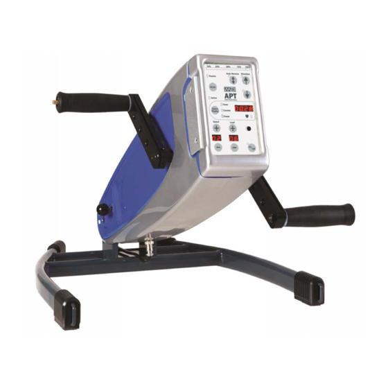
4. SYSTEM COMPONENTS AND DETAILS 4.1. APT PLUS unit (Figure 1) Operator panel Angle release knob Angle securing knob Crank-arm Power input socket Socket (not in use) Height release knob (Hi-Lo only) Height securing knob (Hi-Lo only) 4.2. Primary components (Figure 2): Power supply unit (Provided) Straight hand-grips (Optional accessory) Footrests (Optional accessory) - Page 9 When this equipment is no longer operational it must be sent to a separate collection facility for recovery and recycling. CE approved Notified Body No. 0123. Type B equipment. Read this user manual and all labels before operating. APT PLUS – User’s Manual Rev.B_8/2/13...
- Page 10 The APT PLUS - Operator Panel Figure 3 On/Off button: green indicator is lit when the APT PLUS is switched on. Mode button: for selecting active or passive mode of operation. Green indicator is lit when ACTIVE mode is selected by mode button. Green indicator is lit when PASSIVE mode is selected by mode button.
- Page 11 Green indicator is lit when Power display is selected. The display will show the power during exercise in Watts – only in Active mode. Heart rate monitor Display for Timer, Counter and Energy. Exercise speed level selection push buttons + – Increases speed level (up to 10) (down to 1) - –...
-
Page 12: Accessories
5. ACCESSORIES The following items are designed for use in combination with the APT PLUS. CAUTION: The use of accessories other than these can be unsafe. 5.1 Hand grips and Footrests # ACCESSORY USAGE DESCRIPTION FIGURE Straight Used for most of the upper limb exercising. Handgrips Angled Ergonomically designed, mainly for strength... -
Page 13: Section B - User Information
SECTION B – USER INFORMATION 6. PREPARING THE APT PLUS HI-LO Figure 4 Figure 4A 6.1 Moving your APT PLUS Hi-Lo The APT PLUS Hi-Lo can easily be moved by lifting the end of the frame and pushing the unit using its wheels, see Figure 4. -
Page 14: Installation For Use - Arms Exercise
7. INSTALLATION FOR USE – ARMS EXERCISE Step 1: Position the APT PLUS on a level table top close to an electrical socket outlet (Figure 5). For the APT PLUS Hi-Lo: loosen the height securing knob (Figure 1A-8), pull the grey ring of the height re- lease knob (Figure 1A-7) and adjust the unit to the required height. - Page 15 Step 4: Install the finger protection discs (Fig. 8-1) by sliding them into the grooves on the outside edges of the crank arms (Figure 8-2) in the direction shown. NOTE: The finger protection discs are important for safe operation of the unit during hands exercise. Step 5: Insert handgrip (Figure 9-1) in one of the four mounting holes (Figure 9-2) in each of the APT PLUS crank arms.
-
Page 16: Installation For Use - Legs Exercise
8. INSTALLATION FOR USE – LEG EXERCISE Step 1: Position the APT PLUS on the floor close to an electrical socket outlet (Figure 10). Step 2: Loosen the angle-securing knob (Figure 10-1) and adjust the APT PLUS to the required angle. To increase the angle, lift the body of the APT PLUS, allow it to “click”... - Page 17 Step 4: Connect the power output connector (Figure 12-1) of the power supply (Figure 12-4) to the APT PLUS power input socket (Figure 12-2a) while ensuring correct position of connector groove opposite the guide key of socket (Figure 12-2b). NOTE: The APT PLUS must be used only with an original APT PLUS Power Supply unit. Step 5: Insert Footrest (Figure 13-1) in one of the four mounting holes (Figure 13-2) in each of the APT PLUS crank arms.
-
Page 18: Operation Instructions
9. OPERATION INSTRUCTIONS NOTE: Install APT PLUS for arms or legs exercise as described in the previous chapters. 9.1 Active mode - ISOKINETIC operation Step 1: Insert the handgrips or footrests in one of the four mounting holes according to the radius and range of motion required. - Page 19 9.3 PASSIVE mode Step 1: Insert the handgrips or footrests in one of the four mounting holes according to the radius and range of motion required. NOTE: As the effective crank arm length is reduced in the PASSIVE mode, the range of movement is reduced and the degree of resistance that the motor can overcome is increased.
- Page 20 9.4 COMBINED active/passive mode Step 1: Operate the APT PLUS in the passive mode and work against the force of the motor by applying re- sistance to the rotation of the crank arms. Step 2: The resistance force to the rotation is displayed on the on the Bar Indicator as a percentage (%) at each level.
- Page 21 9.6 Display By pressing the button, four different types of data can be displayed. Normally the display will show the time measuring the duration of exercising; the green indi- cator will be lit. Each time the button is pressed, the display will shift to show the next data type – as follows: ...
-
Page 22: Transportation And Storage
9.8 Emergency Switch In the event of the need to stop the APT PLUS quickly, press the red mushroom headed button (Figure 14-1) sit- uated on the top of the trainer body (above the control panel). This will immediately cut the electrical supply to the APT PLUS. -
Page 23: Emi - Electromagnetic Interference
11. EMI – ELECTROMAGNETIC INTERFERRENCE CAUTION: It is important that you read this information regarding the possible effects of electromagnetic interference on your APT PLUS. Electromagnetic Interference (EMI) From Radio Wave Sources The equipment may be susceptible to electromagnetic interference (EMI), which is interfering electromagnetic energy (EM) emitted from sources such as radio stations, TV stations, amateur radio (HAM) transmitters, two-way radios, and cellular phones. - Page 24 APT PLUS – User’s Manual Rev.B_8/2/13...
- Page 25 APT PLUS – User’s Manual Rev.B_8/2/13...
-
Page 26: Section C - Service Information
SECTION C – SERVICE INFORMATION 12. GENERAL MAINTENANCE The expected service life of the APT PLUS is at least 7 years. Minimum ongoing maintenance should prevent unnecessary repairs. The rugged design of the APT PLUS and the use of selected, modern materials ensure minimal requirements for care and maintenance. -
Page 27: Disposing And Recycling
13. DISPOSAL AND RECYCLING The packing material must be separated to plastic and paper/cardboard components and submitted to authorized re- cycling locations. The APT PLUS device consists of electronic components, cables, plastic parts, steel body and base frame, and alu- minium parts. -
Page 28: Appendix - Exercise Parameter Values
15. APPENDIX – EXERCISE PARAMETER VALUES Table 1: Active Mode ISOKINETIC operation Speed (RPM) Bar Graph Force (Kg) Power (Watt) 100% Level Speed Force Power Watts 15.4 25.6 Force Power Watts 10.3 19.2 33.3 Force 11.3 Power Watts 11.5 25.0 43.6 Force 10.0... - Page 29 10.0 20.0 10.8 21.6 11.2 22.4 11.6 23.2 12.2 24.4 NOTE: Force Levels are indicated for Mounting Hole locations R1, R2, R3 & R4 on crank-arms (Figure 9 / Figure 13). APT PLUS – User’s Manual Rev.B_8/2/13...
- Page 30 16. WARRANTY The warranty period for the APT PLUS is twelve months and covers faulty materials and workmanship (consumables not covered: plastic coverings and batteries). Worn parts damaged as a result of excessive loading, improper han- dling, intentional damage or unauthorized maintenance or modification are not covered by the warranty. For safety and for warranty assurance reasons, any modifications and repair of the APT PLUS or its components must be performed exclusively by authorized personnel and exclusively with original spare parts.
Need help?
Do you have a question about the APT PLUS 8200 and is the answer not in the manual?
Questions and answers