Table of Contents
Advertisement
Quick Links
Advertisement
Table of Contents

Subscribe to Our Youtube Channel
Related Manuals for MSI MS-7314


Summary of Contents for MSI MS-7314
- Page 1 Wind Board MS-7314 (v1.X) Mainboard G52-73141X1...
-
Page 2: Trademarks
Alternatively, please try the following help resources for further guidance. Visit the MSI website for FAQ, technical guide, BIOS updates, driver updates, an d oth er in forma tion : htt p:// glob al.m si.com.tw /ind ex.p hp? -
Page 3: Safety Instructions
Safety Instructions Always read the safety instructions carefully. Keep this User’s Manual for future reference. Keep this equipment away from humidity. Lay this equipment on a reliable flat surface before setting it up. The openings on the enclosure are for air convection hence protects the equip- ment from overheating. -
Page 4: Fcc-B Radio Frequency Interference Statement
VOIR LA NOTICE D’INSTALLATION AVANT DE RACCORDER AU RESEAU. Micro-Star International MS-7314 This device complies with Part 15 of the FCC Rules. Operation is subject to the following two conditions: (1) this device may not cause harmful interference, and (2) this device must accept any interference received, including interference that may cause undesired operation. -
Page 5: Weee (Waste Electrical And Electronic Equipment) Statement
WEEE (Waste Electrical and Electronic Equipment) Statement... -
Page 8: Table Of Contents
CONTENTS Copyright Notice ....................ii Trademarks ......................ii Revision History ....................ii Technical Support ....................ii Safety Instructions ....................iii FCC-B Radio Frequency Interference Statement ........... iv WEEE (Waste Electrical and Electronic Equipment) Statement ........ v Chapter 1. Getting Started ................1-1 Mainboard Specifications ................ -
Page 9: Chapter 1. Getting Started
Getting Started Chapter 1 Getting Started Thank you for choosing the Wind Board (MS-7314 v1. X) Micro-ATX mainboard. The Wind Board is based on ® Intel brand new Atom CPU and 945GC + ICH7 chipsets for optimal system efficiency. The Wind Board delivers a high performance and professional desktop platform solution. -
Page 10: Mainboard Specifications
MS-7314 Mainboard Mainboard Specifications Processor Support ® - Intel ATom series Celeron 230 processor in the LGA437 package Supported FSB - 533 MHz Chipset ® - North Bridge: Intel 945GC chipset ® - South Bridge: Intel ICH7 chipset Memory Support - 2 DDR2 DIMMs support DDR2 533/ 667 SDRAM (240pin / 1.8V) - Page 11 Getting Started Connectors Back panel - 1 PS/2 mouse port - 1 PS/2 keyboard port - 1 Parallel port - 1 Serial port - 1 VGA port - 4 USB 2.0 Ports - 1 LAN jack - 3 flexible audio jacks On-Board Pinheaders / Connectors - 2 USB 2.0 pinheaders - 1 chassis intrusion connector...
-
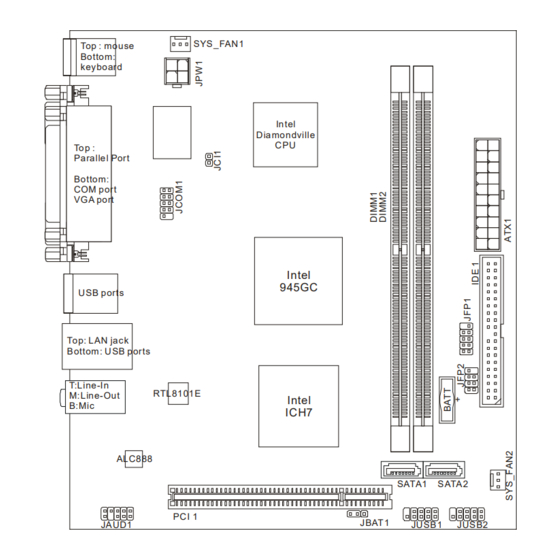
Page 12: Mainboard Layout
COM port VG A port Intel 945GC U SB ports Top: LAN jack Bottom : U SB ports Line-In RTL8101E Line-Out Intel ICH7 ALC888 SATA1 SATA2 PC I 1 JBAT1 JAUD1 JU SB1 JUSB2 Wind Board (MS-7314 v1.X) Micro-ATX Mainboard... -
Page 13: Packing Checklist
Getting Started Packing Checklist Back IO Shield MSI Driver/Utility CD MSI motherboard Power Cable SATA Cable IDE Cable User’s Guide and Quick Guide * The pictures are for reference only and may vary from the packing contents of the product you purchased. -
Page 14: Chapter 2. Hardware Setup
Hardware Setup Chapter 2 Hardware Setup This chapter provides you with the information about hardware setup procedures. While doing the installation, be careful in holding the components and follow the installation procedures. For some components, if you install in the wrong orientation, the components will not work properly. -
Page 15: Quick Components Guide
MS-7314 Mainboard Quick Components Guide JCOM1, SYS_FAN1, p.2-14 p.2-13 DDR2 DIMMs, JCI1, JPW1, p.2-7 p.2-3 p.2-15 ATX1, p.2-7 Back Panel, p.2-10 JFP1, p.2-15 IDE1, p.2-12 JFP2, p.2-15 SATA, p.2-13 SYS_FAN2, p.2-13 JUSB1~2, p.2-16 JAUD1, PCI, JBAT1, p.2-14 p.2-18 p.2-17... -
Page 16: Memory
Hardware Setup Memory These DIMM slots are used for installing memory modules. For more information on compatible components, please visit http://global.msi.com. tw/index.php?func=testreport DDR2 240-pin, 1.8V 56x2=112 pin 64x2=128 pin Installing Memory Modules 1. The memory module has only one notch on the center and will only fit in the right orientation. - Page 17 MS-7314 Mainboard Important - DDR2 memory modules are not interchangeable with DDR and the DDR2 standard is not backwards compatible. You should al ways instal l DDR2 memory modules in the DDR2 DIMM slots. - To enable successful system boot-up, always insert the memory modules into the DIMM1 first.
- Page 18 Hardware Setup Compatible DDR2 667 memory list Please refer to the following list to find the available DDR2 memory modules. Vendor Model Size Micron MT4HTF3264AY-667D3 (MICRON D9GMG) 256MB M378T3253FZ3-CE6 (SEC K4T56083QF-ZCE6) 256MB ADATA ADQPE1908 (ADATA AD29608A8A-3EG) 512MB AENEON AET660UD00-30DB97X (AENEON AET93R30DB) 512MB Apacer 78.91G92.9K5 (Apacer AM4B5708JQJS7E)
- Page 19 MS-7314 Mainboard Vendor Model Size AENEON AET860UD00-30DB08X (AENEON AET03F30DB) Apacer 78.A1G9O.9K4 (Apacer AM4B5808CQJS7E) D2U667C-2GMEJ (Micron D9HNL) Buffalo Select CORSAIR VALUESELECT VS2GB667D2 (Micro D9HNL) Crucial CT25664AA667.16FA (Micron D9FTB) HYNIX HYMP125U64CP8-Y5 (HYNIX HY5PS1G831CFP-Y5) Micron MT16HTF25664AY-667E1 (Micron D9HNL) NANYA NT2GT64U8HB0JY-3C (NANYA NT5TU128M8BJ-3C) Qimonda...
-
Page 20: Power Supply
Hardware Setup Power Supply ATX 20-Pin Power Connector: ATX1 This connector allows you to connect to an ATX power supply. To connect to the ATX power supply, make sure the plug of the power supply is inserted in the proper orientation and the pins are aligned. - Page 21 MS-7314 Mainboard Compatible Power Supply list Please refer to the following list to find the available power supplies. Vendor Model Spec. Asus ATX-250YA 20+4pin; 250W 勁霸傳奇 GoldenField ATX-300WB 20+4pin; 300W 勁馳 JC-B323ATX 20+4pin; 323W 世紀之星 風雲 ATX325 20+4pin; 325W DELUX DLP-328A 20+4pin;...
- Page 22 24pin; 450W Golden field ATX-S600 24pin; 600W Huntkey HK650-11PEP 24pin; 650W Seventeam ST-750EAJ-05G 24pin; 750W Important 1. For more information on compatible components, please visit http://global. msi.com.tw/index.php?func=testreport. 2. Power supply of 500 watts (and lower) is strongly recommended for system stability.
-
Page 23: Back Panel
MS-7314 Mainboard Back Panel Parallel Port Mouse Line-In Line-Out Keyboard USB Port Serial Port USB Port VGA Port Mouse/Keyboard ® ® The standard PS/2 mouse/keyboard DIN connector is for a PS/2 mouse/keyboard. Parallel Port A parallel port is a standard printer port that supports Enhanced Parallel Port (EPP) and Extended Capabilities Parallel Port (ECP) mode. - Page 24 Hardware Setup Audio Ports These audio connectors are used for audio devices. It is easy to differentiate be- tween audio effects according to the color of audio jacks. Line-In (Blue) - Line In is used for external CD player, tapeplayer or other audio devices.
-
Page 25: Connectors
MS-7314 Mainboard Connectors IDE Connector: IDE1 This connector supports IDE hard disk drives, optical disk drives and other IDE devices. Important If you install two IDE devices on the same cable, you must configure the drives separately to master / slave mode by setting jumpers. Refer to IDE devi ce’s documentation suppl i ed by the vendors for jumper setting... - Page 26 Hardware Setup Serial ATA Connector: SATA1~2 This connector is a high-speed Serial ATA interface port. Each connector can connect to one Serial ATA device. SATA1 SATA2 Important Please do not fold the Serial ATA cable into 90-degree angle. Otherwise, data loss may occur during transmission. Fan Power Connectors: SYS_FAN1/ SYS_FAN2 The fan power connectors support system cooling fan with +12V.
- Page 27 MS-7314 Mainboard Serial Port Connector: JCOM1 This connector is a 16550A high speed communication port that sends/receives 16 bytes FIFOs. You can attach a serial device. Pin Definition SIGNAL DESCRIPTION Data Carry Detect Serial In or Receive Data SOUT Serial Out or Transmit Data...
- Page 28 Hardware Setup Front Panel Connectors: JFP1, JFP2 These connectors are for electrical connection to the front panel switches and LEDs. ® The JFP1 is compliant with Intel Front Panel I/O Connectivity Design Guide. JFP1 Pin Definition SIGNAL DESCRIPTION HD_LED + Hard disk LED pull-up FP PWR/SLP MSG LED pull-up...
- Page 29 MS-7314 Mainboard Front USB Connector: JUSB1~2 ® These connectors, compliant with Intel I/O Connectivity Design Guide, is ideal for connecting high-speed USB interface peripherals such as USB HDD, digital cameras, MP3 players, printers, modems and the like. Pin Definition SIGNAL...
-
Page 30: Jumper
Hardware Setup Jumper Clear CMOS Jumper: JBAT1 There is a CMOS RAM onboard that has a power supply from an external battery to keep the data of system configuration. With the CMOS RAM, the system can auto- matically boot OS every time it is turned on. If you want to clear the system configuration, set the jumper to clear data. -
Page 31: Slot
MS-7314 Mainboard Slot PCI (Peripheral Component Interconnect) Slot The PCI slot supports LAN card, SCSI card, USB card, and other add-on cards that comply with PCI specifications. 32-bit PCI Slot Important When adding or removing expansion cards, make sure that you unplug the power supply first. -
Page 32: Chapter 3 Bios Setup
BIOS Setup Chapter 3 BIOS Setup This chapter provides information on the BIOS Setup program and allows you to configure the system for optimum use. You may need to run the Setup program when: ² An error message appears on the screen during the system booting up, and requests you to run SETUP. -
Page 33: Entering Setup
MS-7314 Mainboard Entering Setup Power on the computer and the system will start POST (Power On Self Test) process. When the message below appears on the screen, press <DEL> key to enter Setup. Press DEL to enter SETUP If the message disappears before you respond and you still wish to enter Setup, restart the system by turning it OFF and On or pressing the RESET button. - Page 34 BIOS Setup Control Keys <↑> Move to the previous item <↓> Move to the next item <←> Move to the item in the left hand <→> Move to the item in the right hand <Enter> Select the item <Esc> Jumps to the Exit menu or returns to the main menu from a submenu <+/PU>...
-
Page 35: The Main Menu
MS-7314 Mainboard The Main Menu Standard CMOS Features Use this menu for basic system configurations, such as time, date etc. Advanced BIOS Features ® Use this menu to setup the items of AMI special enhanced features. Integrated Peripherals Use this menu to specify your settings for integrated peripherals. - Page 36 BIOS Setup Load Optimized Defaults Use this menu to load the default values set by the mainboard manufacturer specifi- cally for optimal performance of the mainboard. Save & Exit Setup Save changes to CMOS and exit setup. Exit Without Saving Abandon all changes and exit setup.
-
Page 37: Standard Cmos Features
MS-7314 Mainboard Standard CMOS Features The items in Standard CMOS Features Menu includes some basic setup items. Use the arrow keys to highlight the item and then use the <PgUp> or <PgDn> keys to select the value you want in each item. - Page 38 BIOS Setup Device / Vendor / Size It will showing the device information that you connected to the SATA connector. LBA/Large Mode This allows you to enable or disable the LBA Mode. Setting to Auto enables LBA mode if the device supports it and the devices is not already formatted with LBA mode disabled.
- Page 39 MS-7314 Mainboard System Information Press <Enter> to enter the sub-menu, and the following screen appears. This sub-menu shows the CPU information, BIOS version and memory status of your system (read only).
-
Page 40: Advanced Bios Features
BIOS Setup Advanced BIOS Features Full Screen Logo Display This item enables this system to show the company logo on the bootup screen. Settings are: [Enabled] Shows a still image (logo) on the full screen at boot. [Disabled] Shows the POST messages at boot. Quick Booting Setting the item to [Enabled] allows the system to boot within 10 seconds since it will skip some check items. - Page 41 MS-7314 Mainboard Primary Graphic’s Adapter This setting specifies which graphic card is your primary graphics adapter. PCI Latency Timer This item controls how long each PCI device can hold the bus before another takes over. When set to higher values, every PCI device can conduct transactions for a longer time and thus improve the effective PCI bandwidth.
- Page 42 BIOS Setup DVMT Mode Select This item allows you to set the mode for the graphics core. [Fixed] mode, a fixed-size fragment of the system memory is allocated to the graphics core. It can only be used by the graphics core. [DVMT] mode, the driver of the graphics core uses the system memory like any other OS component or application does.
-
Page 43: Integrated Peripherals
MS-7314 Mainboard Integrated Peripherals USB Controller This setting allows you to enable/disable the onboard USB controller. USB Device Legacy Support Select [Enabled] if you need to use a USB-interfaced device in the operating system. Onboard LAN Controller This item is used to enable/disable the onboard 1st LAN controller (Realtek 8111B, the one next to the USB connector). - Page 44 BIOS Setup On-Chip IDE Controller These items allow users to enable or disable the IDE controller. PCI IDE BusMaster This item allows you to enable/ disable BIOS to used PCI busmastering for reading/ writing to IDE drives. On-Chip SATA Controller These items allow users to enable or disable the SATA controller.
-
Page 45: Power Management Setup
MS-7314 Mainboard Power Management Setup Important S3-related functions described in this section are available only when your BIOS supports S3 sleep mode. ACPI Function This item is to activate the ACPI (Advanced Configuration and Power Management Interface) Function. If your operating system is ACPI-aware, such as Windows 2000/ XP, select [Enabled]. - Page 46 BIOS Setup Power Button Function This feature sets the function of the power button. Settings are: [Power On/ Off] The power button functions as normal power off button. [Suspend] When you press the power button, the computer enters the suspend/sleep mode, but if the button is pressed for more than four seconds, the computer is turned off.
- Page 47 MS-7314 Mainboard Resume By Onboard LAN When set to [Enabled], the feature allows your system to be awakened from the power saving modes through onboard LAN. Resume By RTC Alarm The field is used to enable or disable the feature of booting up the system on a scheduled time/date.
-
Page 48: H/W Monitor
BIOS Setup H/W Monitor Chassis Intrusion The field enables or disables the feature of recording the chassis intrusion status and issuing a warning message if the chassis is once opened. To clear the warning message, set the field to [Reset]. The setting of the field will automatically return to [Enabled] later. -
Page 49: Bios Setting Password
MS-7314 Mainboard BIOS Setting Password When you select this function, a message as below will appear on the screen: Type the password, up to six characters in length, and press <Enter>. The password typed now will replace any previously set password from CMOS memory. You will be prompted to confirm the password. -
Page 50: Cell Menu
BIOS Setup Cell Menu Important Change these settings only if you are familiar with the chipset. Current CPU / DRAM Frequency These items show the current clocks of CPU and Memory speed. Read-only. Advance DRAM Configuration Press <Enter> to enter the sub-menu and the following screen appears. Configure DRAM Timing by SPD Setting to [Auto] enables DRAM CAS# Latency automatically to be determined by BIOS based on the configurations on the SPD (Serial Presence Detect) EEPROM... - Page 51 MS-7314 Mainboard CAS# Latency (CL) When the Configure DRAM Timing by SPD sets to [Manual], the field is adjustable. This controls the CAS latency, which determines the timing delay (in clock cycles) before SDRAM starts a read command after receiving it.
- Page 52 BIOS Setup Important 1. If you do not have any EMI problem, leave the setting at [Disabled] for optimal system stability and performance. But if you are plagued by EMI, select the value of Spread Spectrum for EMI reduction. 2. The greater the Spread Spectrum value is, the greater the EMI is reduced, and the system will become less stable.
-
Page 53: Load Fail-Safe/ Optimized Defaults
MS-7314 Mainboard Load Fail-Safe/ Optimized Defaults The two options on the main menu allow users to restore all of the BIOS settings to the default Fail-Safe or Optimized values. The Optimized Defaults are the default values set by the mainboard manufacturer specifically for optimal performance of the mainboard.
Need help?
Do you have a question about the MS-7314 and is the answer not in the manual?
Questions and answers