Yamaha RX-397 Service Manual
Hide thumbs
Also See for RX-397:
- Owner's manual (206 pages) ,
- Owner's manual (206 pages) ,
- Owner's manual (37 pages)
Table of Contents
Advertisement
This manual has been provided for the use of authorized YAMAHA Retailers and their service personnel.
It has been assumed that basic service procedures inherent to the industry, and more specifically YAMAHA Products, are already
known and understood by the users, and have therefore not been restated.
WARNING:
IMPORTANT:
The data provided is believed to be accurate and applicable to the unit(s) indicated on the cover. The research, engineering, and service
departments of YAMAHA are continually striving to improve YAMAHA products. Modifications are, therefore, inevitable and
specifications are subject to change without notice or obligation to retrofit. Should any discrepancy appear to exist, please contact the
distributor's Service Division.
WARNING:
IMPORTANT:
CONTENTS
TO SERVICE PERSONNEL . . . . . . . . . . . . . . . . . . . . 2
IMPEDANCE SELECTOR . . . . . . . . . . . . . . . . . . . . . . 3
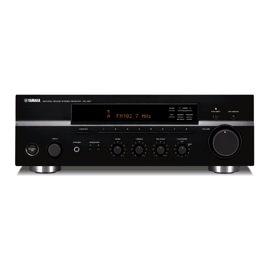
FRONT PANEL . . . . . . . . . . . . . . . . . . . . . . . . . . . . . . 3
REAR PANELS . . . . . . . . . . . . . . . . . . . . . . . . . . . . 4-5
REMOTE CONTROL PANEL . . . . . . . . . . . . . . . . . . . 5
SPECIFICATIONS . . . . . . . . . . . . . . . . . . . . . . . . . . 6-7
INTERNAL VIEW . . . . . . . . . . . . . . . . . . . . . . . . . . . . . 7
DISASSEMBLY PROCEDURES . . . . . . . . . . . . . . . . . 8
SELF DIAGNOSIS FUNCTION . . . . . . . . . . . . . . . 9-15
© 2005 YAMAHA CORPORATION. All rights reseved.
1 0 0 9 7 8
This manual is copyrighted by YAMAHA and may not be copied or
redistributed either in print or electronically without permission.
STEREO RECEIVER
RX-397
IMPORTANT NOTICE
Failure to follow appropriate service and safety procedures when servicing this product may result in personal
injury, destruction of expensive components, and failure of the product to perform as specified. For these reasons,
we advise all YAMAHA product owners that any service required should be performed by an authorized YAMAHA
Retailer or the appointed service representative.
The presentation or sale of this manual to any individual or firm does not constitute authorization, certification or
recognition of any applicable technical capabilities, or establish a principle-agent relationship of any form.
Static discharges can destroy expensive components. Discharge any static electricity your body may have
accumulated by grounding yourself to the ground buss in the unit (heavy gauge black wires connect to this buss).
Turn the unit OFF during disassembly and part replacement. Recheck all work before you apply power to the unit.
AMP ADJUSTMENT . . . . . . . . . . . . . . . . . . . . . . . . . 16
IC DATA . . . . . . . . . . . . . . . . . . . . . . . . . . . . . . . . 17-18
DISPLAY DATA . . . . . . . . . . . . . . . . . . . . . . . . . . . . . 19
PIN CONNECTION DIAGRAM . . . . . . . . . . . . . . . . . 20
PRINTED CIRCUIT BOARD . . . . . . . . . . . . . . . . 21-27
BLOCK DIAGRAM . . . . . . . . . . . . . . . . . . . . . . . . . . . 28
SCHEMATIC DIAGRAM . . . . . . . . . . . . . . . . . . . 29-31
REMOTE CONTROL RAX16 . . . . . . . . . . . . . . . . . . 33
PARTS LIST . . . . . . . . . . . . . . . . . . . . . . . . . . . . . 34-42
SERVICE MANUAL
SERVICE MANUAL
'05.11
Advertisement
Table of Contents

Related Manuals for Yamaha RX-397


Summary of Contents for Yamaha RX-397
-
Page 1: Table Of Contents
This manual has been provided for the use of authorized YAMAHA Retailers and their service personnel. It has been assumed that basic service procedures inherent to the industry, and more specifically YAMAHA Products, are already known and understood by the users, and have therefore not been restated. -
Page 2: To Service Personnel
RX-397 TO SERVICE PERSONNEL AC LEAKAGE 1. Critical Components Information EQUIPMENT WALL TESTER OR Components having special characteristics are marked Z OUTLET UNDER TEST EQUIVALENT and must be replaced with parts having specifications equal to those originally installed. 2. Leakage Current Measurement (For 120V Models Only) -
Page 3: Impedance Selector
RX-397 IMPEDANCE SELECTOR WARNING: Do not change the setting of the IMPEDANCE SELECTOR switch when the unit power is switched on, as doing so may damage the unit. IMPEDANCE SELECTOR FRONT PANEL... -
Page 4: Rear Panels
RX-397 REAR PANELS U, C models R model A model... -
Page 5: Remote Control Panel
RX-397 G, E models L model REMOTE CONTROL PANEL RAX16... -
Page 6: Specifications
RX-397 SPECIFICATIONS AUDIO SECTION Usable Sensitivity (IHF) Mono ....... 1.0 µV (11.2 dBf) Minimum RMS Output Power (Power Amp. -
Page 7: Internal View
RX-397 DIMENSIONS 435 (17-1/8") Unit : mm (inch) INTERNAL VIEW OPERATION (12) P.C.B. (A, G, E, L models) MAIN (4) P.C.B. (R, L models) MAIN (2) P.C.B. MAIN (3) P.C.B. MAIN (1) P.C.B. MAIN (5) P.C.B. FUNCTION (4) P.C.B. FUNCTION (1) P.C.B. -
Page 8: Disassembly Procedures
RX-397 DISASSEMBLY PROCEDURES • Remove parts in disassembly order as numbered. • Disconnect the power cable from the AC outlet. 1. Removal of Top Cover 4. Removal of Sub Chassis Unit a. Remove 4 screws ( ), 1 screw ( ) and 4 screws ( a. -
Page 9: Self Diagnosis Function
RX-397 SELF DIAGNOSIS FUNCTION This product has a built-in self diagnosis function (DIAG) to facilitate inspection, measurement and determination of a faulty item, if any. There are 8 DIAG menu items, each having sub-menu items. No. DIAG menu Sub-menu DISPLAY CHECK 1. - Page 10 RX-397 Starting DIAG Display provided when DIAG started Press the “STANDBY/ON” key of the main unit while simul- On the FL display of the main unit, an opening mes- taneously pressing the “FM/AM” key and the “8” key to acti- sage (including the version and the protection history) vate the DIAG function.
- Page 11 RX-397 Operation procedure of DIAG MENU and The protection function worked due to a DC voltage ap- pearing at the speaker terminal. SUB-MENU A cause could be a defect in the amplifier. If the power is There are 8 MENU items, each of which has some SUB- turned on with the abnormality unsolved, the protection func- MENU items.
- Page 12 RX-397 1. DISPLAY CHECK 2. FACTORY PRESET This program is used to check the FL display section. The This menu is used to reserve/inhibit initialization of the back- display condition varies as shown below according to the up RAM. sub-menu operation.
- Page 13 R, A, G, E, L 87.5 87.50 500% display of the voltage based on the temperature de- 90.1 90.10 tected value. Reference voltage: 5V 95.1 95.10 * For RX-397, only R ch is effective. A/C/E 98.1 98.10 107.9 108.00 88.1 88.10 THM:L000 R098 106.1...
- Page 14 RX-397 5. PROTECTION SETTING 6. PROTECTION HISTORY This menu is used to change the protection setting value. Four protection histories are display. The change is effective in this menu only. A set value can The history is cleared by the initialization reservation of DIAG be specified between 0 –...
- Page 15 RX-397 7. SOFT SWITCH 8. MICROPROCESSOR INFORMATION The version, checksum and the port specified by the Note) Changing the function setting may hinder the proper microprocessor are displayed. The checksum is obtained operation. by adding the data at every 16 bits for each program area and expressing the result as a 4-figure hexadecimal This menu is used to switch the function settings on P.C.B.
-
Page 16: Amp Adjustment
RX-397 AMP ADJUSTMENT CONFIRMATION OF IDLING CURRENT 1. Right after the power is turned on, confirm that the volt- age across the terminals of R137 (L ch) and R138 (R ch) are between 0.1mV to 10.0mV. 2. If the measured voltage exceeds 10.0mV, open (cut off) R131 (L ch), R132 (R ch) and reconfirm the voltage. -
Page 17: Ic Data
RX-397 IC DATA IC602 : M30626FHPFP (FUNCTION (2) P.C.B.) 16-bit Microprocessor P07/D7 P44/CS0 P06/D6 P45/CS1 P05/D5 P46/CS2 P04/D4 P47/CS3 P03/D3 P50/WRL/WR P02/D2 P51/WRH/BHE P01/D1 P52/RD P00/D0 P53/BCLK P107/AN7/K13 P54/HLDA P106/AN6/K12 P55/HOLD P105/AN5/K11 P56/ALE P104/AN4/K10 P57/RDY/CLKOUT P103/AN3 P60/CTS0/RTS0 P102/AN2 P61/CLK0 P101/AN1... - Page 18 RX-397 IC602 : M30626FHPFP (FUNCTION (2) P.C.B.) 16-bit Microprocessor Port Name Function P64/CTS1/RTS1/CTS0/CLKS1 AF220 BUSY Signal Output P63/TXD0/SDA0 DTIS Input Selector Tx DATA P62/RXD0/SCL0 CEIS Input Selector CE P61/CLK0 CKIS Input Selector CLOCK P60/CTS0/RTS0 DTRZ Rec/Zone2 selecter DATA (Unconnected) P57/RDY/CLKout...
-
Page 19: Display Data
RX-397 DISPLAY DATA V801 : 15-BT-105GNK (WF519900) PATTERN AREA PIN CONNECTION Note 1) F1, F2 ..Filament 2) NP ....No Pin 3) NX ....No Extend Pin 4) P1~P35 ..Datum Line 5) 1G~15G ..Grid GRID ASSIGNMENT ANODE CONNECTION... -
Page 20: Pin Connection Diagram
RX-397 PIN CONNECTION DIAGRAM LM61CIZ NJU7201L55 TLP421 TC4013BP NJM2068MD LC72722PM 3: GND 3: GND 2: Vout 2: VIN 1: VOUT 1: +Vs NJU7313AM LB1641 M66003-0131FP M30626FHPFP Diodes 1SS355 1SS133 S1NB20 S4VB20 1SS380 1SS270A S1NB60 MA8056-M 1SR139 MA8051-M MA8120-H MTZJ16A UDZS5.1BTE-17 MTZJ6.8B... - Page 21 RX-397 PRINTED CIRCUIT BOARD FUNCTION (1) P.C.B. FUNCTION (4) P.C.B. (Side A) FUNCTION (2) FUNCTION (2) (Side A) CB603 CB602 (REC) REMOTE TAPE (PLAY) (REC) (PLAY) FUNCTION (1) W505 CD/DVD FUNCTION (4) CB781 FUNCTION (4) P.C.B. FUNCTION (1) P.C.B. (Side B) Lead Free Solder Used...
-
Page 22: Printed Circuit Board
RX-397 PRINTED CIRCUIT BOARD FUNCTION (2) P.C.B. (Side A) OPERATION (1) OPERATION (2) OPERATION (13) TUNER PACK CB801 CB401 CB301 OPERATION (2) CB407 FUNCTION (2) Circuit No. U, C R, L G, E R613 IC603 XL602 C630, 632 C622, 623... - Page 23 RX-397 PRINTED CIRCUIT BOARD OPERATION (1) P.C.B. (Side A) OPERATION (10) CB810 A/B/C/D/E OPERATION (7) CB815 FUNCTION (2) CB606 TUNING EDIT MEMORY MODE FM/AM TUNING OPERATION (5) MAIN (1) CB814 CB103 OPERATION (1) P.C.B. (Side B) Lead Free Solder Used...
- Page 24 RX-397 PRINTED CIRCUIT BOARD OPERATION (2) P.C.B. OPERATION (3) P.C.B. (Side A) (Side A) FUNCTION (2) FUNCTION (2) CB611 W601 OPERATION (2) W405 LOUDNESS BALANCE TREBLE BASS OPERATION (3) P.C.B. (Side B) Lead Free Solder Used MAIN (1) CB107 OPERATION (3)
- Page 25 RX-397 PRINTED CIRCUIT BOARD OPERATION (5) P.C.B. OPERATION (7) P.C.B. OPERATION (8) P.C.B. OPERATION (9) P.C.B. (Side A) (Side A) (Side A) (Side A) OPEARTION (1) OPERATION (1) CB807 OPERATION (2) W806 CB403 PURE DIRECT SPEAKERS INPUT STANDBY/ON OPERATION (7) P.C.B.
- Page 26 RX-397 PRINTED CIRCUIT BOARD Lead Free Solder Used MAIN (1) P.C.B. MAIN (5) P.C.B. (Side A) (Side A) MAIN (1) Circuit No. A, G, E, L U, C, R C156–159, 161, 162 X: NOT USED O: USED/APPLICABLE POWER TRANSFORMER POWER...
- Page 27 RX-397 PRINTED CIRCUIT BOARD Lead Free Solder Used MAIN (2) MAIN (2) P.C.B. MAIN (3) P.C.B. Circuit No. U, C G, E J252 POWER CABLE (Side A) (Side A) CB253, 254 F251 TE251 W293 ST254 X: NOT USED O: USED/APPLICABLE...
-
Page 28: Block Diagram
RX-397 BLOCK DIAGRAM RY103 OPERATION • See page 30 → SCHEMATIC DIAGRAM C834,835 Head Phone FM/AM IC401 2,29 12,19 RY101 TUNER Motor Volume Muting Power Front A Q401,402 VR431/IC431 FM/AM 7.2MHz C157,158 3,28 /MIMT Pure Direct SW PHONO EQ PHONO... - Page 29 RX-397 SCHEMATIC DIAGRAM (FUNCTION) IC501: NJU7313AM Analog Function Switch L-COM1 R-COM1 R-COM2 L-COM2 L-COM3 R-COM3 DATA CONTROL 18 NC Page 31 Page 30 Page 30 TO MAIN (1) W103 TO OPERATION (1) CB801 TO OPERATION (13) CB301 CD/DVD 10.1 5.4 5.4 11.9...
-
Page 30: Schematic Diagram
RX-397 SCHEMATIC DIAGRAM (OPERATION) IC301, 401, 751: NJM2068MD-TE Dual OP-Amp 14.5 13.1 13.1 –IN – – –IN –V PURE DIRECT OFF -14.4 14.0 -14.4 PURE DIRECT OFF PURE DIRECT ON -14.0 IC431: LB1641 Motor Driver IC801: M66003-0131FP Display Driver Display code... - Page 31 RX-397 SCHEMATIC DIAGRAM (MAIN) IC102 : LM61CIZ Temperature Sensor Vout AC4.2 Page 30 TO POWER TRANSFORMER TO OPERATION (1) W801 Page 29 TO FUNCTION (2) CB605 25.5 25.5 25.5 25.5 14.5 32.2 32.1 32.1 32.2 15.1 25.5 44.9 15.1 (32.8) 25.5...
-
Page 32: Remote Control Rax16
SCHEMATIC DIAGRAM ZONE3 ZONE2 KI/O6 KI/O5 KI/O4 KI/O7 KI/O3 S1/LED KI/O2 47Ω KI/O1 KI/O0 XOUT 4.00MHz 1Ω 47µF YAMAHA RAX16 IR CODE TABLE Code (ID2) DEVICE Key Name (RDS) TAPE SLEEP 7D-93 POWER 7D-B2 CD/DVD 7D-87 PHONO 7D-88 TUNER 7D-89 STANDBY... -
Page 33: Parts List
RX-397 PARTS LIST WARNING ELECTRICAL PARTS Components having special characteristics are marked Z and must be replaced with parts having specifications equal to those originally installed. ABBREVIATIONS IN THIS LIST ARE AS FOLLOWS : C.A.EL.CHP : CHIP ALUMI. ELECTROLYTIC CAP L.EMIT... - Page 34 RX-397 P.C.B. FUNCTION & OPERATION Part No. Description Market Part No. Description Market WG054100 P.C.B. FUNCTION D607 VT332900 DIODE 1SS355 WG054200 P.C.B. FUNCTION D608 VU993000 DIODE.ZENR MA8056‑M 5.6V WG054300 P.C.B. FUNCTION D609 VU996300 DIODE.ZENR MA8120‑H 12.3V WG054400 P.C.B. FUNCTION D781 VT332900 DIODE 1SS355 CB501 V7827600 SOCKET 9P SE TUC SERIES...
- Page 35 RX-397 P.C.B. OPERATION Part No. Description Market Part No. Description Market CB814 VB858400 CN.BS.PIN 5P IC401 X3505A00 IC NJM2068MD‑TE2 C303‑304 UA652220 C.MYLAR 220pF 50V J IC431 XF494A00 IC LB1641 C307‑308 UU318220 C.EL 220uF 6.3V IC751 X3505A00 IC NJM2068MD‑TE2 C309‑310 UA654330 C.MYLAR 0.033uF 50V J IC801 X6386A00 IC M66003‑0131FP...
- Page 36 RX-397 P.C.B. MAIN Part No. Description Market Part No. Description Market WG052800 P.C.B. MAIN C257 UA653100 C.MYLAR 1000pF 50V J WG052900 P.C.B. MAIN C258 WB696300 C.POL.MTL 0.1uF 400V WG053000 P.C.B. MAIN C258 WF081500 C.PP 0.047uF 630V J RAGEL WG053100 P.C.B. MAIN C258 WF081500 C.PP 0.047uF 630V J WG053200 P.C.B.
- Page 37 RX-397 P.C.B. MAIN & CHIP RESISTORS Part No. Description Market Part No. Description Market Q252‑253 iC1815I0 TR 2SC1815 Y R.CHP 0Ω 1/16W J Z Q254 WC741200 FET 2SK3850 R.CHP 2.2Ω 1/16W J Z R113‑114 HV754470 R.CAR.FP 47Ω 1/4W R.CHP 47Ω 1/16W J R127‑128 HV756270 R.CAR.FP 2.7KΩ 1/4W R.CHP 82Ω 1/16W J R131‑132 HV756100 R.CAR.FP 1KΩ 1/4W...
- Page 38 RX-397 Parts List for Carbon Resistors Value 1/4W Type Part No. 1/6W Type Part No. Value 1/4W Type Part No. 1/6W Type Part No. 1.0 Ω 3100 3100 7100 10 kΩ 7100 HJ35 HF85 HF45 HF45 1.8 Ω 3180 7110 11 kΩ...
- Page 39 RX-397 EXPLODED VIEW 200-1 2-122 2-120 7 (5) 7 (3) 7 (1) 7 (10) 2-122 2-122 2-121 2-50 7 (7) 2-120 2-120 7 (8) 7 (2) 2-20 2-20 2-70 2-30 2-121 2-120 2-40 7 (9) 7 (4) 2-120 (12) 6 (2)
- Page 40 RX-397 MECHANICAL PARTS Ref. Part No. Description Remarks Markets * 1‑1 WF478400 FRONT PANEL * 1‑1 WF478600 FRONT PANEL * 1‑4 WF486800 ESCUTCHEON R * 1‑4 WF487000 ESCUTCHEON R 1‑5 WF628900 ESCUTCHEON 1‑5 WF629100 ESCUTCHEON 1‑6 V6034100 EMBLEM 1‑7 V4598900 LENS, 1P * 1‑8 MF121250 FLEXIBLE FLAT CABLE 21P 250mm P=1.25...
- Page 41 RX-397 Ref. Part No. Description Remarks Markets * 103 WF482600 REAR PANEL * 103 WF482700 REAR PANEL * 103 WF482900 REAR PANEL VS025000 LEG D60xH21 VR264400 SPACER VQ366100 DAMPER, PCB WF817400 KNOB D48 WF817600 KNOB D48 * 112 WF485600 KNOB * 112 WF485800 KNOB * 113 WF485900 KNOB D14L * 113 WF486100 KNOB D14L...
Need help?
Do you have a question about the RX-397 and is the answer not in the manual?
Questions and answers